
Review Article Volume 4 Issue 3
UAV systems for multipurpose heterogeneous networks: a review of design, development and performance
Yeinson-Alfonso Castellanos-Sanabria,1 German-Wedge Rodriguez-Pirateque2 
Regret for the inconvenience: we are taking measures to prevent fraudulent form submissions by extractors and page crawlers. Please type the correct Captcha word to see email ID.

1Department of Aeronautics Engineering, Fundacion Universitaria Los Libertadores, Colombia
2Department of Mechanics and Mechatronics Engineering, Universidad Nacional de Colombia, Colombia
Correspondence: German-Wedge Rodriguez-Pirateque, Department of Mechanics and Mechatronics Engineering, Universidad Nacional de Colombia, Bogota D.C, Colombia, Tel 3015590546
Received: July 21, 2020 | Published: August 19, 2020
Citation: Castellanos-Sanabria YA, Rodríguez-Pirateque GW. UAV systems for multipurpose heterogeneous networks: a review of design, development and performance. Aeron Aero Open Access J. 2020;4(3):121-139. DOI: 10.15406/aaoaj.2020.04.00114
Download PDF
Abstract
The technological fusion between wireless sensor networks and the UAS capabilities allows a fast, easy, and inexpensive deployment with multipurpose heterogeneous networks like a communication system for replicable nodes. For a UAV proposed, this paper studies the heterogeneous communication networks with their design, development, and performance where the configurations and design requirements, systems, subsystems required, preliminary sizing study, and services and capabilities were analyzed. Consequently, preliminary dimensions such as wingspan, length, height, maximum take-off weight, and performance specifications were obtained to give introductory considerations about the avionics, routing protocols, and human interaction which infers in an implementation challenge but with several advantages in military and civil applications.
Keywords: UAS, UAV, design, heterogeneous networks, wireless sensor networks, civil and military applications
Abbreviations
UAS, unmanned aircraft systems; UAV, unmanned aerial vehicle; RPAS, remotely piloted aircraft system; ART, remotely manned aircraft; QFD, quality function deployment; VLOS, visual line of sight; BVLOS, beyond the visual line of sight; MEMS, microelectromechanical systems; ISR, intelligence, surveillance, and reconnaissance; LIDAR, light detection and ranging or laser imaging detection and ranging; IMU, inertial measurement unit; GPS, global positioning system; EO/IR, sensor systems (day and night); SAR, synthetic aperture radar
Introduction
The human factor is the most important asset for military and civil institutions, where Research and Development (R&D) is the main tool to improve it. Recently, aviation has ventured into the UAV implementation to decrease the risk of harming human resources.1 UAVs is used in many applications, such as river searching and tracking,2 border patrol and surveillance,3 generating real-time hazard maps,4 forest firefighting before, during, and after the accident,5 monitoring gas transmission pipelines,6 operational oil spill surveillance, monitoring and assessment,7 structure inspections,8 disaster relief operations,9 monitoring and surveillance,10 logistics,11 agriculture,12 environmental monitoring,13 military field (reconnaissance, monitoring, intelligence, combat and surveillance),14 and detection of the chemical and biological natural resources.15 Although the mentioned applications are very useful, their implementing, testing, and operating introduce several technical challenges.16
Nowadays the UAVs market is focused on the 70% in the military sector, 17% consumer sector, and 13% commercial sector with a total investment of 50 billion dollars by 2050 and more than 1 million units, figure 1.17 According to,18 there are currently 95 countries with UASs active inventory where the number of countries operating UAVs of any kind has increased by an estimated 58% in the past decade. The Guardian newspaper, based on data from Jane's market forecasts, estimates an expense of some $8 billion on units the next decade.19
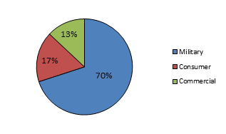
Figure 1 UAVs market by economic sector.
The Unmanned Aerial Vehicle (UAV) or Remotely Manned Aircraft (ART) is a powered vehicle that doesn’t need a human operator. It can be operated autonomously, or by remote control, in a visual line of sight (VLOS) and beyond the visual line of sight (BVLOS). As the main characteristic, it can be recoverable, but it can be expendable; it carries a lethal or non-lethal load; and it can be fixed wing, rotating wing, or lighter than air, figure 2.20,21
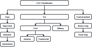
Figure 2 UAV classification.
Diversely, the Unmanned Aircraft System (UAS) or Remotely Piloted Aircraft System (RPAS) is a system integrated by one or more UAVs and all those elements necessary for its operation. It’s set up by an aerial segment with the aerial platform, payload and the communications system; and a ground segment with the launch and recovery elements, deployment and protection equipment, the station and control system, and the communication devices.20 It’s characterized by low-cost operation, rapid placement, safe access to dangerous areas, and flexible and scalable deployment.22
In specific, there are many ways to classify the UASs due to great diversity in missions, and the regulatory method used to group in a simplified way different UASs and their systems, table 1.
Class (MTOW) |
Category |
Use |
Normal Operating Altitude |
Mission Radius |
Class I≤150kg |
Micro < 2 kg |
Tactical, (section) |
Up to 200 ft. |
5 km (VLOS) |
Mini 2-20 kg |
Tactical, (Company) |
Up to 1000 ft. |
25 km (VLOS) |
Light > 20 kg |
Tactical, (Battalion) |
Up to 1200 ft. |
200 km (VLOS) |
Class II≤600kg |
Tactical |
Tactical, (Brigade) |
Up to 10000 ft. |
No limit (BLOS) |
Class III>600kg |
MALE (Medium Long Endurance) |
Operational |
Up to 45000 ft. |
No limit (BVLOS) |
HALE (High Altitude Long Endurance ) |
Strategic |
Up to 65000 ft. |
No limit (BVLOS) |
Combat |
Strategic |
Up to 65000 ft. |
No limit (BVLOS) |
Table 1 NATO UAS classification
Globally, the United States is the most important UAS manufacturer along with Israel, Russia, and China, figure 4. Latin American presents a growing trend allowing a percentage of world production about 81,3% for Class I, and 18,7% for Class II and III, figure 3.23-25 Since 2006, Colombia has dabbled in the UAV uses with the acquisitions of Israeli and American UAVs mainly, which are focused on military forces and joint task forces necessities.26 The several advantages in the military field have aroused interest to manufacture the UAV Quimbaya, UAV Iris, UAV Coelum, Tarsis 75, Tarsis 25, Navigator X-2,27 a partnership between Spain to develop the Atlante 2,18 and other more researches,28,29 table 2.
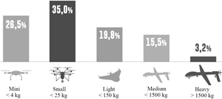
Figure 3 Percentage of UASs world production.
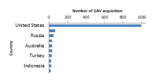
Figure 4 UAV acquisition forecast over the next 10 year.
|
Research team
|
Publication year
|
Tittle
|
Remarks
|
|
Kim et al.30
|
2017
|
On Collision-free reinforced barriers for multi domain IoT with heterogeneous UAVs
|
The maximum movement of UAVs with the creation of virtual lines in multi-domain on condition was minimized.
|
|
Kumar et al.31
|
2017
|
New secure routing protocol with elliptic curve cryptography for military heterogeneous wireless sensor networks
|
Uses of elliptic curve cryptography to discover trusted neighbors with an efficient key management mechanism that provides better security.
|
|
Secure multiple routes for reliable data delivery was established.
|
|
Low communication overhead, memory requirement, and low energy consumption were achieved.
|
|
Carapau et al.32
|
2017
|
Unmanned aerial systems in military environments: The benefits of interoperability
|
The importance and motivation for the use of UAVs with their primary military applications were shown.
|
|
An approach to interoperability is presented: its concept, and a project that has proved its reliability, converging to the benefits
|
|
Mallick & Satpathy33
|
2018
|
Challenges and Design Goals of Wireless Sensor Networks: A State-of-the-art Review
|
The structure, characteristics of a wireless sensor network, and its prospective applications along with its implementation challenges as well as design goals were surveyed.
|
|
Liao et al.34
|
2019
|
Launching an unmanned aerial vehicle remote sensing data carrier: concept, key components and prospects
|
A UAV network capable of dynamic obtaining very high-resolution remote sensing images with a pilot retrieval system of UAV Metadata was developed.
|
|
Qin et al.35
|
2019
|
Trajectory Planning for Data Collection of Energy-Constrained Heterogeneous UAVs
|
A multiple heterogeneous UAVs with different energy constraints to maximize the data collection utility were considered.
|
|
Under different network settings, the performance of the proposed trajectory planning algorithm is evaluated via simulations.
|
Table 2 State-of-art summary
Followed this; there are several studies about UAVs uses due to the technological advancement, table 2 and figure 5.30 The authors present collision-free reinforced barriers by heterogeneous UAVs minimizing maximum movement with the creation of virtual lines in multi-domain on condition.31 The authors have proposed a new secure multipath routing protocol for military heterogeneous wireless sensor networks which uses elliptic curve cryptography to provide better security and improves the network achieving low communication overhead, memory requirement, and low energy consumption.

Figure 5 Heterogeneous UAVs systems networks state-of-art timeline.
Similarly, in32 is studied the impact of UAVs in military environments and how interoperability can further develop the benefits in its use. In33 the authors surveyed the structure, characteristics of a wireless sensor network, and its prospective applications along with its implementation challenges as well as design goals. In,34 this paper describes a seamless docking with UAVs. The data carrier forms a national UAV network capable of dynamic obtaining very high-resolution remote sensing images with a pilot retrieval system of UAV Metadata.
In,35 the authors have considered multiple heterogeneous UAVs with different energy constraints to maximize the data collection utility where the trajectory planning algorithm is evaluated via simulations.
In this way, according to The United States of America Department of Defense (DOD), the interoperability is the ability that systems, units, and forces have to provide and receive services to develop the joint operation effectiveness.36,37 Thus, several UAVs equipped with sensors can be deployed without the need of multiple pilots and decreased performance to extend the capability through the integration of heterogeneous systems that work together.
This potential can be further developed when paired with other unmanned systems (space, ground, surface, and underwater), promoting the study of a military joint task force interoperability and its benefits, table 3.22 Their applications could be in collaborative surveillance missions, detection and tracking of enemy forces, escorting and monitoring operations, spotting improvised explosive devices (IEDs), communication relays, interception, air-to-air superiority missions, and detection of hazardous biological, chemical, and/or explosive.25,32,38
|
Strengths
|
Weaknesses
|
|
· Useful for 4D task “dull, dirty, dangerous and deep”.
|
· Limited ability to integrate weapons into class I and II systems.
|
|
· They allow avoid human risks.
|
· Vulnerability to cyber-attacks.
|
|
· They can be cheaper (attention to life cost).
|
· Regulations under development.
|
|
· Increase operational availability.
|
· War law norms can limit higher levels of autonomy.
|
|
· Class I and Class II provide immediate information if the radio space is not congested.
|
· Adaptation to airworthiness regulations can increase development costs.
|
|
· They reduce personnel in the areas of operations.
|
· Integration into non-segregated airspace is costly and uncertain.
|
|
· Increase the duration of the mission.
|
· They present difficulties of social acceptance in some areas (personal data protection).
|
|
· They can extend the networks lifetime.
|
· Need for development in maritime environments.
|
|
· They don’t require a fixed infrastructure.
|
· UAVs lack a unified space-time framework and standardized data process.
|
|
· They allow dynamic, self-configurable, and highly adaptive mobile ad hoc networks.
|
· The computational complexity in the task coupling.
|
|
· They may be used in low and high threat environments.
|
· Communication architecture types.
|
| |
· Rate requirements.
|
| |
· Bandwidth requirements and frequency spectrum allocation.
|
| |
· Security requirements and reliability requirements.
|
|
Opportunities
|
Threats
|
|
· They can enhance technological and industrial development.
|
· Loss of industrial sovereignty if its development is not promoted.
|
|
· Potential for development and experimentation of new operational concepts in both the military and civilian spheres.
|
· From the political point of view, it can make them useless if strategies neither are nor addressed global.
|
|
· Growing civil market.
|
· Short-term financial situation requires establishing medium/long strategies.
|
|
· Quick and cheaper entry into service than for systems manned.
|
· Lack of funds for technological development.
|
|
· They allow the establishment of complete operating networks.
|
· Pressures to develop large systems can drown the development of smaller and more efficient systems.
|
|
· UAVs could surpass satellites and manned aircraft in sensing data with high resolution, high coverage area, and heterogeneous multi-sources.
|
· High accident rates.
|
|
|
· Large bandwidth and radioelectric spectrum management.
|
Finally, the introduction section presents the UAVs world production market summary, state-of-art, applications, advantages, and disadvantages. Following, the research methodology section presents the type of methodology used by authors and how it was synthesized. The configurations and design requirements section presents general aspects of avionics, landing gear, fuselage, main wing, tail, propulsion system, and complementary information to show the large variety in accessories, layouts y recommendations to achieve the best UAV sizing. This above section is complemented by the systems and subsystems section, which show the general considerations about needs and routing protocols, heterogeneous network reflections, and propulsion and flight control systems deliberations.
Next the sensitivity studies and preliminary estimates section offerings the sizing initial considerations to approach the comparative study of similar airplanes supported by the quality function deployment matrix information. To finish, the services and capabilities section presents the main recommendations in UAV specialties, UAV military tasks, assumptions for any country needs, government policy deliberations, and human interaction considerations.
Research methodology
This review article is the systematic review type in which was identified, evaluated, and synthesized all information about UAVs heterogeneous networks with papers from 2010 until 2020. The databases consulted were IEEE Xplore Digital Library, Progress in Aerospace Sciences, Academy Google and Science, college repositories, Air Power Journal, and military and civil news portals.
Consequently, the information was evaluated and synthesized by a QFD Matrix, and thus, was identified the UAV necessities focused on requirements, recommendations, design baseline, and technical solutions based in the aeronautical bibliography.
Configurations and design requirements
The UAV's design should respond to reducing manning, this results in a control of multiple heterogeneous UAVs to a small number of human operators, and thus, low workload, low military inactivity, and war field misunderstanding.39 Consequently, each UAV concept is a complex problem that requires a different design approach according to infrastructure conditions, weather conditions, geographical conditions, technology available, pilots’ skills, air defense, national security conditions, and flight-paths conditions, under minimum specifications such as:22
- Human interaction.
- A long autonomously controlled flight at low temperatures.
- Easy transported out and into the flight stations.
- Good payload capacity with a strong, light, and suitable structure.
- A powerful engine with easy operation and maintenance.
Avionics considerations
In general, UAVs avionics systems are lighter, more compact and simpler than their manned aircraft versions. From standard aviation avionics, these avionics systems are similar. Only under specialized requirements, the development of some avionics systems is dedicated to UAVs.25
Likely, supported by redundant safety systems, the most important parts of the onboard system are IMUs (Inertial Measurement Unit) combined with the GPS signal processor, transponder, engine controller system, electronically scanned array radars, VHF communication and navigation systems, thermal vision cameras, LIDAR sensor, RGB color sensor, infrared sensors, multispectral and hyper-spectral observation sensor systems (day and night) EO/IR, video tracking systems, high-resolution SAR and ISAR radars, signal intelligence (SIGINT), communication intelligence (COMINT), a longer range and high-resolution ISR sensors, and sensors to detect and avoid collisions using ultrasonic, infrared, time-of-flight vision, 3D-positioning, and real-time detection, figure 6.40,41
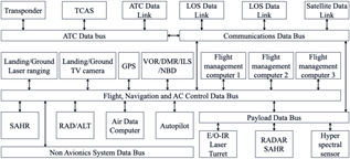
Figure 6 Avionics system schematic example.
Landing gear considerations
The landing gear absorbs impact loadings from landings and guarantees stability at the taxi phase, which must be three times the UAV weight.42 The tricycle configuration will accomplish these needs, adding that the engine and propeller could be protected from ground strikes.43 Unlike, there are innovative configurations, such as catapults or rocket assistance for take-off, and nets or parachutes for landing. Other configurations combine some or all of the helicopter characteristics with a wing fixed aircraft, but they represent mechanically complex solutions with attendant weight and cost penalties.44
Fuselage considerations
The composite materials and payload have become standard for fuselage construction with the 3D printing of structural elements. Ensuring their proper cooling, the fuselage must focus on aerodynamic and the dynamic and static stability behavior without decreases the flight performance to obtain the lowest air resistance and the necessary volume for avionics system installation, electro-optical equipment, engine, landing gear, airfoils, and fuel tank o battery storage.45 So, from the designer's knowledge, the internal layout is very a very important task, as it affects stability, static margin, center of gravity, maintenance, and functionality.43,51,52
Main wing consideration
The wing development is a multistage task that includes: airfoil selection, geometrical calculations, structural design, materials selection, numerical analysis, and manufacturing.46 The main task is to design structure characterized by high strength along with low weight which optimizes the performance, lateral stability, and lift generation with aerodynamic coefficients studies by CFD software or wind tunnel.47 Under the considerations of along autonomously controlled flight and good payload capacity, the most efficient configuration is a monoplane high fixed-wing. This configuration will tolerate a stable flight with the possibility to use a rectangular, mixed o tapered wings and winglets. This could be improved by a fly-by-wire power transmission in primary/secondary controls, high lift devices, and a sweep and dihedral angle, supported by previous studies.43
Another wing configuration could be a blended wing body. The UAV would have better aerodynamics efficiency because the wings are blended with the fuselage, eliminating the additional drag to create up to 60% of the lift, and therefore, it needs less power, and less fuel is burned. Another advantage is its interior space and its useable volume with a lighter and smaller structure that allows more payload ability. The disadvantage is that it does not incorporate a tail section which leads to potential flight stability and maneuverability issues. It is possible to correct it through the use of custom airfoils, winglets, the center of gravity optimal placement, and the use of many control surfaces.48
Tail considerations
In a conventional layout, the tail configuration establishes the maneuverability, trim and stability. For this reason, the wing-fuselage-tail combination affects the UAV performance, where an optimal and strict software evaluation must be done with a fixed or adjustable tail to ensure pitch moment, center of gravity longitudinal location, and engine location. The conventional or inverted V-tail configuration saves weight and reduces the surface area, so thus produces less induced and parasitic drag with the configuration of a primary controls most complex, focused on longer rear fuselages. Unlike, the T-tail is kept out of the disturbed airflow, giving smoother and faster airflow over the elevator, but the UAV would able to suffer a dangerous deep stall condition. The conventional tail is the most lightweight construction with the adjustable tail option, but with low spin characteristics due to the blanketing of the vertical tail, and a high downwash, figure 7. Finally, any layout configuration will determine the primary control surface method, such as conventional (elevator, aileron, and rudder), elevon/rudder, aileron/ruddervator, or flaperon/rudder/aileron.43

Figure 7 Tail configurations alternatives.
Propulsion system considerations
The pusher configuration allows to keep clean the UAV front to install cameras and sensors, the engine and propeller aren't exposed to a direct hit to the ground, and the airflow isn’t projected to the control surfaces, which allows laminar flow reducing the resistance, increasing the maneuverability and stability. Unlike, the tractor configuration releases the flow over the main wing, tail, and fuselage generating drag and making a flow turbulent.29
Another important item is the longitudinal and lateral UAV equilibrium. In a conventional configuration, the engine is a good counterweight because it makes the batteries or fuel tank to be located on the center of gravity without affecting the trim condition. While in the pusher configuration, the batteries, and fuel tanks are responsible for the correct trim model because the rear engine emphasizes the weight on the tail, which makes that the distribution of batteries, payload, and components is in the front to make a counterweight.29,49
Complementary considerations
Another configuration exists and it’s pertinent to take into account. That is the hybrid UAV which can be generally categorized into two main types: convertiplanes (tilt-rotors, tilt-wings, rotor-wings, and dual-systems) and tail-sitters (ducted-fan UAVs, control surface transitioning tail-sitters, differential thrust transitioning tail-sitters, and reconfigurable wings).50
Systems and subsystems required
General considerations
Nowadays, computational intelligence, sensor coordinating technologies, and operations analysis systems allow devising and managing heterogeneous mobile networks to obtain a variety of cooperative wireless networks.53 These networks maximize the size of the area covered according to the sensors power, sensors placement, number of sensors, type of sensors, energy protocols, power efficiency and optimization, and network topology control.38
UAVs integrate technologies such as aeronautics, robotics, and electronics.54 The keys in their development trends are MEMs devices, miniaturization of observation systems, and satellite communication and transmission systems25 with challenges such as path length, optimality, completeness, cost-efficiency, time-efficiency, energy efficiency, robustness, and collision avoidance,1 which can be improved by an efficient energy source, structural hardware, computing hardware, and autonomous software.55
Thereby, the UAS functions, services, and requirements must be focused on communication among UAVs, communications relay nodes, UAVs as networks gateways, assisted sensing, assisted acting, data storage, data processing, and Distributed versus centralized control16 where the UAS must be divided in three main parts, figure 8.32
- Ground control station, command, communication subsystem, launch and recovery subsystem, and support equipment.
- Datalink system: uplink (land-to-air), downlink (air-to-land).
- The vehicle includes the payload, a navigation subsystem, sensors, communication subsystem, and propulsion (combustion, all-electric, or hybrid).
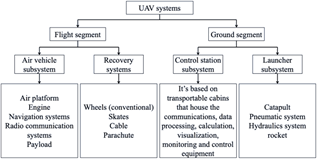
Figure 8 UAS systems considerations.
On the other hand, it is recommended that the UASs components be as follows:1
- Global positioning system module: It computes the longitude, time, location, latitude, elevation, compass, navigation and autonomous flight system.
- Flight controller: It controls the network communications by the GPS module, light amplification by stimulated emission of radiation (LASER) monitors and other sensors.
- Energy storage system: it controls the electrical network and to ensure its reliable operation.
- Gimbal: It provides stabilization for taking good photographs and videos.
- Sensors: It detects events or changes in its environment to sends the information; its quality is measured through coverage concerning the speed and altitude.56
Routing protocols considerations
Routing protocols specify how UAVs make communication between their central data unit and ground station, for this purpose the system must be equipped with high-gain omni-directional antennas to minimize path loss and make a signal to noise ratio higher.57 It can be categorized in static, proactive, reactive, hybrid, and hierarchical, where their choice depends on the number of UAVs, on-board processing capabilities, on-board memory, storage capacity, UAVs energy and power capability, GPS capability, robustness, security, and degree of UAVs mobility.16
A UAV, as a node, can perform like a mobile ad hoc network with the IEEE 802.11 and IEEE 802.15.4 protocol,58 typically on 2.4 GHz to 5.2 GHz with a minimum 12 dBi gain.57 These protocols have a reasonable communication range, support sense multiple access with collision avoidance, and use a distributed coordination and the point coordination to provide support for real-time multimedia data traffic. Their recent upgrades (IEEE 802.11n, IEEE 802.11s, IEEE 802.11g, IEEE 802.11b, and IEEE 802.11ac) develop longer communication ranges and high data rates. Also, if it is a need the internet use, with the IEEE 802.16 protocols (WLAM and WWAN) one UAV can play the role of a gateway node.16
Heterogeneous network considerations
The intelligence, surveillance, and reconnaissance (ISR) can be achieved from fixed assets (radars, sensors, or cameras), moving assets (aircraft, UASs, satellites, or a constellation of them), or a combination of both.59,60 In general, a heterogeneous network (mobile ad hoc network) allows monitoring via video cameras, sensors, and radars with different sensing capabilities, different flight speeds and overlap to detect objects that might be visible in one medium but not other, so it is a resilient and cost-effective solution to extend the coverage area and operation speed.38,61
The main advantages are the low cost, miniaturized size, easy deployment, high lifetime, low energy consumption, low movement of nodes, and high data communications efficiency. It's sensing, actuating, communicating and processing capabilities enable wireless mobility, self-organize, flexibility, and communication in difficult access areas with embedded controllers, memory units, communication devices, and power supplies. Due to real-time data, voice, and communication capabilities, it must be considered the architectures, the number of nodes deployed, and the loss of nodes with a redundant system that restores the data transfer.
Figure 9 gives a coarse view of the structure with military purposes:62
- Collaboration: This layer enables the collaboration between nodes by flight plan optimization.
- Detection: This layer gathers the information needed about objects, events, and their relationship. Each node carries a payload to perform the analysis tasked.
- Exploitation: This layer relates intelligence databases and gathered data to deduce actions.
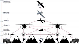
Figure 9 Military heterogeneous wireless network.
According to the above, this system is composed of a ground control station, heterogeneous UAVs, and ground, maritime, and air manned units.63 It can operate in a multilevel cooperation where the ground control station is in charge of the mission control, intelligence, and mission decision making.62 It consists of a wireless router, a computer, a user interface with a compatibility with different platforms,64 open system architecture, execution of data in real-time, ability to control multiple UAVs, payload control, communication with other ground control stations, warning systems, and emergency action plan.57
About this network type, the cooperation between space, ground, and air nodes could improve the availability and functionality where any node can assume the role of cluster heads connecting the ground and space nodes directly to the control station.65 Additionally, one UAV cannot perform all tasks; therefore each UAV could need a specific operator.66
Propulsion system considerations
Diesel and internal combustion propulsion offers optimal thermal efficiency and good behavior during high-altitude flight, due to the turbocharger system.67 The fuel is converted into a power by engines to move the UAV. The remainder power is converted into four main forms of non-propulsive power: pneumatic power, mechanical power, hydraulic power, and electrical power; the best consideration could be electric power aiming to decrease the weight, maintenance, and production cost.68
The electric engine (fans and propeller) allows a very precise speed control, high efficiency, high reliability, reduced noise, longer life-time, and no ionizing spark.67 Finally, taking account of energy storage, hybrid propulsion must be considered due to its benefits with areas to improve such as weight, volume, cost, and reliability.
Under the safety requirements, cost, duration of production, ease manufacturing, and lifecycle must be considered energy source type, number tanks, cells or batteries, location, structural configuration, center of gravity, attachment method, material, assembly technique, external tanks, and a possible air refueling system (figures 10, 11, and 12).43
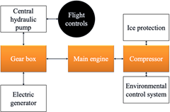
Figure 10 Conventional engine architecture.
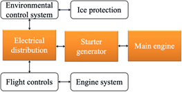
Figure 11 Electric engine architecture.
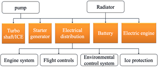
Figure 12 Hybrid engine architecture.
Flight control system consideration
The flight control system (primary/secondary flight controls), vertical/horizontal stabilizer and landing gear front actuation system must be governed by electrical power actuators which drives a pump, fan, or actuator under position, speed, torque and flow design requirements, figure 13.69
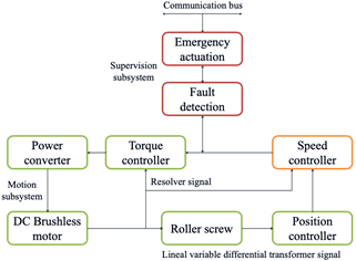
Figure 13 Architecture for electro-mechanic actuators
It is correct to affirm that the flight control system must work along with an automatic pilot system where sometimes this flight dynamic could be autonomous under the operator supervision.55 The whole system must be supported by decentralized and redundant architecture to maintain a high level of safety. In case of a fault, it would be possible to perform automatic checking to predict future maintenance revisions, introducing the predictive maintenance instead of preventive maintenance.70
Sensitivity studies and preliminary estimates
Preliminary sizing
It is mandatory to conduct sensitivity studies to find out which parameters will drive the UAV design, determining the areas of technological change to be proposed, and from an optimistically or pessimistically consideration, to provide a quick estimate impact on the design. Typically, this study is carried on regard to payload
, empty weight
, range (R), endurance (E), lift-to-drag ratio
, specific fuel consumption (
or
), and propeller efficiency
.71
Therefore, this sensitivity study is applied to a UAV class I propelled by single-engine propellers with the FAR 23 certification base, table 1.71 So, the mission parameters specifications will be a range of 446.6 nm and a cruise speed of 48.8 knots, according to UAV baseline calculations, table 8:
- Determination of the mission payload weight,
:
(1)
- Estimate of a likely value of takeoff weight,
:
(2)
This value is obtained by comparing the average take-off weight of Class I type UAVs, table 8.
- Determination of the mission fuel weight,
(Table 4, Figure 14):
- Engine start and Warm-Up.
- Taxi.
- Takeoff.
- Climb and accelerate.
- Cruise.
- Loiter.
- Descent.
- Landing, Taxi and Shutdown.
|
|
Engine start, Warm-up
|
Taxi
|
Takeoff
|
Climb
|
Descent
|
Landing, Taxi, Shutdown
|
|
Mission phase
|
1
|
2
|
3
|
4
|
7
|
8
|
|
Single engine
|
0.995
|
0.997
|
0.998
|
0.992
|
0.993
|
0.993
|
Table 4 Suggested fuel-fractions for several mission phases

Figure 14 Mission profile for an arbitrary airplane.
The next fuel-fractions are defined as the ratio of end weight to begin weight, assigning a numerical value to each phase:
Phase 1: Engine start and warm-up
(3)
Phase 2: Taxi
(4)
Phase 3: Takeoff
(5)
Phase 4: Climb to cruise altitude and accelerate to cruise speed
(6)
Phase 5: Cruise
Next,
is the range studied of 446.6 nm, under the restrictions (table 5):
(7)
(8)
|
|
L/D
|
Cp
|
ηp
|
|
Single engine airplane
|
8-10
|
0.5 – 0.7
|
0.8
|
Table 5 Suggested values for L/D, Cp, ηp, and for for several mission phases
Phase 6: Loiter
In the equation 9,
is the loiter endurance of 0.25 h under authors considerations:
(9)
(10)
Phase 7: Descent
(11)
Phase 8: Landing, taxi and shutdown
(12)
It is now possible to calculate the mission fuel-fraction,
from:
(13)
(14)
Thus, the value for the mission fuel weight can finally be determined, assuming the mission reserve fuel-fraction is 0.25 or the 25% of
.
(15)
(16)
(17)
(18)
- Calculation of a tentative value for:
(19)
(20)
- Calculation of tentative value for
from:
The weight of all trapped (unusable) fuel and oil
is assumed as 0.5 % of
:
(21)
(22)
- Determination of the allowable value of empty weight,
(Table 6):
(23)
(24)
|
Airplane Type
|
A
|
B
|
|
Single engine propeller driven
|
-0.144
|
1.1162
|
Table 6 Regression line constants A and B
- Comparison between
and:
The tolerance between
and
of 0.5 % is usually sufficient at this stage.
(25)
Sensitivity studies
(Table 7)
|
Reserve fuel fraction (Mres)
|
0.25
|
|
Mission fuel-fraction (Mff)
|
0.875
|
|
Trapped (unusable) fuel and oil fraction (Mtfo)
|
0.005
|
|
Payload Weight (WPL)
|
46.3 lbs.
|
(26)
(27)
(28)
(29)
- Sensitivity of takeoff weight to payload weight:
(30)
(31)
This means, that for each pound of payload added, the takeoff weight will have to be increased by 3.44 lbs. This assumes that the mission performance stays the same.71
- Sensitivity of takeoff weight to empty weight:
(32)
(33)
This means, that for each pound of increase in empty weight, the takeoff weight must be increased by 1.44 lbs., to keep the mission performance the same.71
(34)
(35)
- Sensitivity of takeoff weight to range:
(36)
(37)
The significance of this partial is as follows. Suppose that the range in the mission specification is changed from 446.6 statues miles to 546.6 statues miles. The result just found indicates that this would require an increase in gross weight at takeoff of
.
- Sensitivity of takeoff gross weight to specific fuel consumption:
(38)
(39)
The significance of this finding is as follows. Suppose the engine could be found with a
of 0.5 instead 0.57 (table 5) the takeoff gross weight could then be decreased by
.
- Sensitivity of takeoff gross weight to propeller efficiency:
(40)
(41)
The meaning of this finding is as follows. If the propeller efficiency
could be increased from 0.8 to 0.83 (table 5) the takeoff gross weight would decreased by
.
- Sensitivity of takeoff gross weight to lift-to-drag ratio:
(42)
(43)
This result means that if
could be increased from 8 to 10 (table 5) the takeoff gross weight would come down by 8.45 lbs. It comes as no surprise, that
in a range dominated airplane has a powerful effect on gross weight.51
Comparative study of similar airplanes
According to the UAVs Class I, this comparative study was done. The main assumption was chosen the UAVs of minimum 70 kg of take-off weight, regardless of the lift method (fixed-wing or rotary wing), table 8 and figure 15.
|
Aircraft
|
Dimensional parameters
|
Performance parameters
|
|
AERTEC Solutions RPAS Tarsis 75

|
Wingspan: 5.2 m
|
Wing: Monoplane rectangular fixed Mid-wing.
|
MTOW: 75 kg
|
Engine: 100 cc
|
|
Length: 3.8 m
|
Tail: Twin tail boom.
|
Payload weight: 12 kg
|
Endurance: 12 h
|
|
Height: 0.96 m
|
Engine: Pusher piston prop single-engine, at aft section.
|
Cruise Speed:100 km/h
|
Range: 150 km
|
| |
Landing Gear: Tricycle.
|
|
Santos Lab Jabiru

|
Wingspan: 5 m
|
Wing: Monoplane tapered fixed high-wing
|
MTOW: 75 kg
|
Max Speed: 101.86 km/h
|
|
Length: 2.4 m
|
Tail: V-tail
|
Payload weight: 6 kg
|
Endurance:12 h
|
| |
Engine: Pusher piston prop single-engine, at aft section.
|
Range: 140 km
|
| |
Landing Gear: Tricycle.
|
|
Tekplus aerospace Centauro C30

|
Rotor: 3.5 m
|
Wing: Rotor two blades.
|
MTOW: 85 kg
|
Max Speed: 111 km/h
|
|
Length: 3.35 m
|
Tail: Tail rotor.
|
Payload weight: 20 kg
|
Endurance: 6 h
|
| |
Engine: Single main rotor, inside fuselage mid-section.
|
Range: 75 km
|
| |
Landing Gear: Landing skids.
|
|
Elbit Systems Hermes 90

|
Wingspan: 5.5 m
|
Wing: Monoplane rectangular fixed high-wing
|
MTOW: 115 kg
|
Max Speed: 175.94 km/h
|
|
Length: 4.2 m
|
Tail: Inverted V-tail
|
Payload weight: 25 kg
|
Engine: Alternative (15 hp)
|
|
Height: 1 m
|
Engine: Pusher piston prop single-engine, at aft section.
|
Cruise Speed: 92.6 km/h
|
Endurance: 15 h
|
| |
Landing Gear: Tricycle.
|
Range: 100 km
|
|
CIAC SART Quimbaya

|
Wingspan: 5.24 m
|
Wing: Monoplane rectangular fixed high-wing
|
MTOW: 70 kg
|
Engine: Internal combustion
|
|
Length: 4.11 m
|
Tail: Twin tail boom.
|
Payload weight: 12 kg
|
Endurance: 10 h
|
| |
Engine: Pusher piston prop single-engine, at aft section.
|
Cruise Speed: 100 km/h
|
Range: 130 km
|
| |
Landing Gear: Tricycle.
|
|
Flight Solutions VT-15

|
Wingspan: 4.2 m
|
Wing: Monoplane rectangular fixed high-wing
|
MTOW: 75 kg
|
Max Speed: 185.2 km/h
|
|
Length: 2.8 m
|
Tail: Twin tail boom.
|
Engine: Internal combustion
|
| |
Engine: Pusher piston prop single-engine, at aft section.
|
Endurance: 2 h
|
|
|
Landing Gear: Tricycle
|
Range: 15 km
|
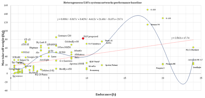
Figure 15 Heterogeneous UAVs systems networks performance.
According to figure 15, the preliminary dimensional and performance parameters are estimated. Thus, this baseline could help to deduce principal design requirements to get any ideas about the main UAV layout with the identification of significant changes with the sensitive study if required.
- The main wing configuration is governed by a rectangular monoplane high fixed-wing with positive or zero dihedral angle, and a wingspan of 4.8 meters.
- The tail configuration is governed by a fixed twin tail boom, located at aft fuselage section. The average length is 3.4 meters with a height of 1 meter.
- The propulsion system configuration is governed by a pusher piston prop single-engine, at aft section. The average power is 15 horsepower to allow a cruise speed of 97.5 km/h, a maximum speed of 143.8 km/h, and an endurance of 9.5 hours.
- The fuselage configuration is governed by a cylindrical layout with a length of 3.4 meters. The landing gear system is a tricycle type which allows a maximum take-off weight of 82.5 kg and 15 kg of payload (Figures 16 & 17).
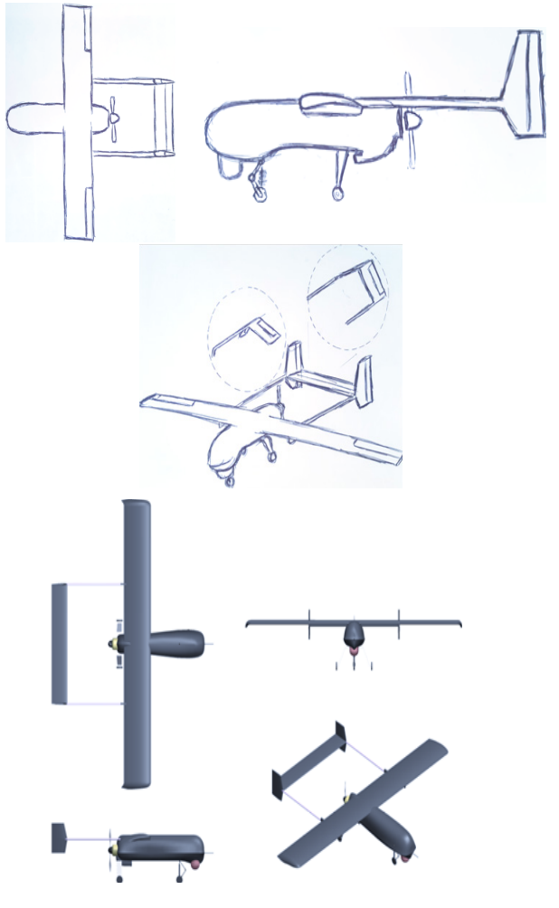
Figure 16 Preliminary sketch 1.
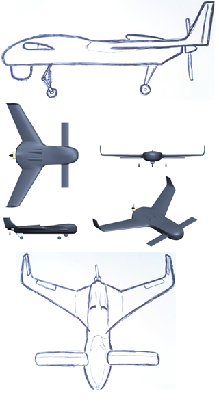
Figure 17 Preliminary sketch 2.
Quality function deployment
The quality function deployment (figure 18) was performed according to demand quality requirements (chapter 3 and 4) to be complemented by the UAV baseline and the preliminary sizing database, table 8. In this order, the following was obtained.
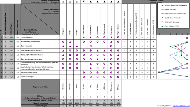
Figure 18 Quality function deployment matrix.
Services and capabilities required for Colombia
General considerations
For the majority of UAVs, their development and exploitation costs are reasonable, which allows their use. Starting from this idea, each country should have its own UASs specialized. The differences are the fuselage structure, power plant, onboard avionics equipment, and payload which is optimized according to the functions and tasks to be performed, therefore, development of UAVs and their markets could increase for an extended range of national or foreign users.25
Mainly, three vehicles specialties on the heterogeneous UASs could be discussed:66
- Surveillance UAV: it can perform intelligence, surveillance, reconnaissance, classification, and verification tasks.
- Combat UAV: with surveillance and attack capabilities, it can perform single or simultaneous attacks with a limited number of weapons on-board, which makes it capable of performing all tasks. If a combat UAV uses up its weapons, it becomes in surveillance UAV.
- Munition UAV: it has the attack capability and can be assigned attack tasks with limited weapons. If a munition UAV uses up its weapons, it can no longer be assigned tasks, a perhaps should return to base.
Generally, the objective is to minimize the cost time of a mission, so there are a maximum number of tasks assigned to any UAV, figure 19. After resources are depleted (weapons, energy, range, etc.), the UAV can no longer be assigned tasks and it must switch into a UAV of another type. This is possible through a mirror representation tool which allows that UAVs with more remaining resources have more chances to be selected and it makes coping with the constraint.66,80
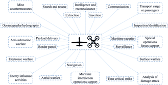
Figure 19 UAVs military tasks.
Information management considerations
Along with computational intelligence, data handling requires methodologies capable of removing redundant information while extracting and processing data. This helps to predict and prevent potential threats. The above involves the creation of software with protocols to guarantee smooth and reliable services and information exchanges which can sense, actuate, process information, and communicate among themselves.32,38
Likewise, collaboration between UAVs evolves at different altitudes. The team may contain multiple satellites, large UAVs covering an area from a high altitude, and low altitude UAVs (fixed-wing, helicopters, or airships).72,73 The decentralized architecture of information will provide automated and robust assistance,74 it raises the capabilities for making efficient and effective decisions due to increased situational awareness and lower workload.62,66 For example, in heterogeneous UASs, if one UAV is destroyed, the information it gathered is contained in the memory on other UAVs; unlike, if the UAV is operating independently, and it was destroyed, the information it had gathered would be lost.61 In short, the whole system is an artificial satellite, being cheaper, closer to the ground, more flexible, self-launched, and be easily recovered.75
Evaluation criteria considerations
The evaluation is essential to support the developments, to materialize their benefits, and thus validate their relevance. In heterogeneous networks, evaluation must be based on the mission scenarios, their constraints, and the types of aircraft used. Thus, quality metrics must be defined about coverage of the area, connectivity, mobility, and energy conservation. This detects false alarm relying on state-of-art simulators, which allows to evaluation from detection to data fusion.62,76 For the sake of accuracy data, it is recommended to have three test assumptions along with their opposite situations:66
- UAVs are survivable and cannot be destroyed while performing tasks.
- UAVs fly at separated altitudes so that they have collision-free paths.
- There are limited but enough resources to perform all tasks (e.g., weapons and fuel).
Engineers must solve limited bandwidth constraints, energy, weapons, memory and processing capabilities, multi-hop, insecure radio communication, communication range, failure scenarios, mobility, network topology, physical size and number of nodes.33
Government policies considerations
According to,77 the productivity gap increases by 70% due to poor decision-making processes, inadequate communication, flawed performance management, bad connection between the different phases of the project, and poor short term planning.78 For solved this, the principal investors, clients, developers, and manufacturers should be determined, including government technology projection programs, national infrastructure, science, and technology institutions. The safety, ethics, privacy right, ownership, and liability impacts must be regulated by implementing national policies, confidentiality policies, and intellectual property protection which could be unified with services standards for information sharing, operation and maintenance, and security standards to ensure interaction and security.34 Although its implementation is a challenge, it allows a reduction of time and cost associated with technological development, motivating productivity and effectiveness, supported by reliability and quality.32
Human interaction considerations
Finally, the “Unmanned Aerial System” term alludes it requires human involvement, from piloting and maintenance to operations, and intelligence. The reader must understand that issues are ranging from remote control and display interfaces to team coordination, automation, and spatial disorientation. Consequently, they are attributed to loss of situation awareness, fatigue, poor team communication, command-and-control efficiency, and automation errors.39
To decrease them, a team of automation, operations, psychology, and maintenance experts must be built to provide the constraints and limitations to address the possible future challenges. These evaluations are aimed at the adaptation in technology, procedures, training, guidance material, certification requirements, and the human/UAV technological relationship.81 The challenge is to determine the adaptations, what forms they should take, how best to achieve and implement them, and how will impact. The success is contingent upon the degree to which human capabilities and limitations match the affordances and constraints.79,82
Conclusion
- Heterogeneous networks must work with ground sensors, manned and unmanned aircraft, and satellites. The fact that they are mobile introduces significant challenges and advantages for future applications, being the preliminary sizing shown a platform to begin to materialize a UAV for multi-agent systems.
- As heterogeneous networks possess stringent resource and design constraints, there is a need to design new wireless networking techniques and protocols to enhance the capabilities of existing architectures.
- The use of wireless networks will make it possible that several hard-to-reach maritime, mountains, and air areas will be full of UAVs. This could provide communication services aiming to resolved technological challenges related to the wireless networks.
- The manpower, personnel, training, environment, safety and occupational health, engineering, survivability, and habitability must be taken into account as systems mature and technology involves. In this way, the UAVs implementation successful will depend on how human systems integrate with the UAVs systems.
Acknowledgments
Conflicts of interest
Authors declare that there is no conflict of interest.
References
- Aggarwal S, Kumar N. Path planning techniques for unmanned aerial vehicles: A review, solutions, and challenges. Computer Communications. 2020;149:270–299.
- Rathinam S, Almeida P, Kim Z, et al. Autonomous searching and tracking of a river using an UAV. American control conference; 2007. 359–364 p.
- Girard AR, Howell AS, Hedrick JK. Border patrol and surveillance missions using multiple unmanned air vehicles. 43rd IEEE Conference on Decision and Control (CDC); 2004.
- Suzuki T, Miyoshi D, Meguro JI, et al. Real-time hazard map generation using small unmanned aerial vehicle. SICE Annual Conference; 2008.
- Ollero A, Merino L. Unmanned aerial vehicles as tools for forest-fire fighting. Forest Ecology and Management. 2006;234(1):S263.
- Hausamann D, Zirnig W, Schreier G. Monitoring of gas transmission pipelines-a customer driven civil UAV application. ODAS Conference; 2003.
- Allen J, Walsh B. Enhanced oil spill surveillance, detection and monitoring through the applied technology of unmanned air systems. International oil spill conference; 2008.
- Pratt K, Murphy RR, Stover S, et al. Requirements for semi-autonomous flight in miniature uavs for structural inspection. AUVSI's Unmanned Systems North America. Orlando, Florida: Association for Unmanned Vehicle Systems International; 2006.
- Sánchez-García J, García-Campos JM, Toral SL, et al. An intelligent strategy for tactical movements of UAVs in disaster scenarios. International Journal of Distributed Sensor Networks. 2016;12(3):8132812.
- Acevedo JJ, Arrue BC, Diaz-Bañez JM, et al. One-to-one coordination algorithm for decentralized area partition in surveillance missions with a team of aerial robots. Journal of Intelligent & Robotic Systems. 2014;74(1-2):269–285.
- Grippa P, Behrens DA, Bettstetter C, et al. Job selection in a network of autonomous UAVs for delivery of goods; 2016.
- Uto K, Seki H, Saito G, e al. Characterization of rice paddies by a UAV-mounted miniature hyperspectral sensor system. IEEE Journal of Selected Topics in Applied Earth Observations and Remote Sensing. 2013;6(2):851–860.
- Erdelj M, Król M, Natalizio E. Wireless sensor networks and multi-UAV systems for natural disaster management. Computer Networks. 2017;124:72–86.
- Maxa JA, Mahmoud MSB, Larrieu N. Survey on uaanet routing protocols and network security challenges; 2017.
- Enos JR, Nilchiani RR. Understanding the importance of expanding the definition of interoperability through social network analysis. Systems Engineering. 2020;23(2):139–153.
- Jawhar I, Mohamed N, Al-Jaroodi J, et al. Communication and networking of UAV-based systems: Classification and associated architectures. Journal of Network and Computer Applications. 2017;84:93–108.
- Castellano F. Commercial Drones Are Revolutionizing Business Operations. Toptal Finance; 2019.
- Gettinger D. Drone databook. Center for the study of the drone. The Drone DataBook; 2019.
- Sabbagh D. Killer drones: how many are there and who do they target?. New York, EU: The Guardian; 2019.
- SPAIN Defense & Security Industry. De los UAV a los RPAS. Madrid, España: InfoDefensa; 2014.
- Resolución número 04201. Bogotá, Colombia: Unidad Administrativa Especial de Aeronáutica Civil, UAEAC; 2018.
- Cooke NJ, Rowe LJ, Bennett Jr W, et al. Remotely piloted aircraft systems: A human systems integration perspective. John Wiley & Sons; 2016.
- Plan estratégico para el desarrollo del sector civil de los drones en España 2018-2021. Madrid, España: Ministerio de Transportes, Movilidad y Agenda Urbana; 2018.
- Sánchez G, Mulera M, Saumeth E. Vehículos aéreos no tripulados en Latinoamérica. Bogotá, Colombia: InfoDefensa; 2013.
- Szczepański C. UAVs and their avionic systems: development trends and their influence on Polish research and market. Aviation. 2015;19(1):49–57.
- Lizarazo MEA. Drones, nuevos panoramas para la aviación: análisis comparativo de la normatividad internacional frente a la normatividad colombiana. Ciencia y Poder Aéreo. 2016;11(1):25–40.
- Soler PLJ. Aeronave no tripulada para reconocimiento y vigilancia aérea: diseño y construcción de un vehículo aéreo no tripulado X-2. TecnoESUFA: revista de tecnología aeronáutica. 2011;15:23–30.
- Gutiérrez Pacheco DS, Rojas Perilla DA, Sánchez González JS. Diseño conceptual de un UAV hibrido anfibio (Aéreo-acuático). Aquatic Unmanned Aerial Vehicle (AQUAUAV); 2017.
- Rocha MA, Solaque LE. Concept design for an unmanned aerial vehicle that will perform exploration missions in Colombia. IFAC Proceedings. 2013;46(30):193–197.
- Kim H, Ben-Othman J, Mokdad L, et al. On Collision-free reinforced barriers for multi domain IoT with heterogeneous UAVs. IEEE 8th Annual Ubiquitous Computing, Electronics and Mobile Communication Conference (UEMCON); 2017.
- Kumar KA, Krishna AV, Chatrapati KS. New secure routing protocol with elliptic curve cryptography for military heterogeneous wireless sensor networks. Journal of Information and Optimization Sciences. 2017;38(2):341–365.
- Carapau RS, Rodrigues AV, Marques MM, et al Unmanned aerial systems in military environments: The benefits of interoperability. Scientific Bulletin” MirceacelBatran” Naval Academy. 2017;20(1):136.
- Mallick C, Satpathy S. Challenges and Design Goals of Wireless Sensor Networks: A State-of-the-art Review. International Journal of Computer Applications. 2018;179(28):42–47.
- Liao X, Yue H, Liu R, et al. Launching an unmanned aerial vehicle remote sensing data carrier: concept, key components and prospects. International Journal of Digital Earth. 2019;1–14.
- Qin Z, Dong C, Wang H, et al. Trajectory Planning for Data Collection of Energy-Constrained Heterogeneous UAVs. Sensors. 2019;19(22):4884.
- Unmanned systems integrated roadmap FY2011-2036. US Department of Defense; 2015.
- Bronk J. The Future of NATO Airpower. Routledge; 2020.
- Ball MG, Qela B, Wesolkowski S. A review of the use of computational intelligence in the design of military surveillance networks. In Recent Advances in Computational Intelligence in Defense and Security: Springer, Cham; 2016. 663–693 p.
- Cooke NJ. Human factors of remotely operated vehicles. In Proceedings of the Human Factors and Ergonomics Society Annual Meeting. Sage CA: Los Angeles; 2006.
- Aasen H, Honkavaara E, Lucieer A, et al. Quantitative remote sensing at ultra-high resolution with UAV spectroscopy: a review of sensor technology, measurement procedures, and data correction workflows. Remote Sensing. 2018;10(7):1091.
- Jordan S, Moore J, Hovet S, et al. State-of-the-art technologies for UAV inspections. IET Radar, Sonar & Navigation. 2018;12(2):151–164.
- Cook S, Brigaud R. Introduction to NATO STANAG 4671-UAV Systems Airworthiness Requirements (Z). AUVSI North America; 2009.
- Sadraey MH. Aircraft design: A systems engineering approach. John Wiley & Sons; 2012.
- Stone H, Wong KC. Preliminary design of a tandem-wing tail-sitter UAV using multi-disciplinary design optimization. AUVSI Proceedings; 1996. 163–178 p.
- Chiesa S, Fioriti M, Fusaro R. MALE UAV and its systems as basis of future definitions. Aircraft Engineering and Aerospace Technology; 2016.
- Figat M, Goetzendorf‐Grabowski T, Goraj Z. Aerodynamic calculation of unmanned aircraft. Aircraft Engineering and Aerospace Technology. 2005;77(6):467–474.
- Grodzki W, Łukaszewicz A. Design and manufacture of umanned aerial vehicles (UAV) wing structure using composite materials. Materialwissenschaft und Werkstofftechnik. 2015;46(3):269–278.
- Thompson D, Feys J, Filewich M, et al. The design and construction of a blended wing body UAV. 49th AIAA Aerospace Sciences Meeting Including the New Horizons Forum and Aerospace Exposition; 2011.
- Brooks C, Salgueiro S. Design Space Investigation for a Small Electric General Aviation Airplane. 55th AIAA Aerospace Sciences Meeting; 2017.
- Saeed AS, Younes AB, Islam S. A review on the platform design, dynamic modeling and control of hybrid UAVs. 2015 International Conference on Unmanned Aircraft Systems (ICUAS); 2015.
- Panagiotou P, Giannakis E, Savaidis G et al. Aerodynamic and structural design for the development of a MALE UAV. Aircraft Engineering and Aerospace Technology. 2018;90(7):1077–1087.
- Frulla G, Cestino E. Design, manufacturing and testing of a HALE-UAV structural demonstrator. Composite Structures. 2008;83(2):143–153.
- Chiesa S, Fioriti M, Viola N. Methodology for an integrated definition of a System and its Subsystems: the case-study of an Airplane and its Subsystems. Systems Engineering–Practice and Theory; 2012. 1–26 p.
- Macke DC, Watkins SE, Rehmeier T. Creative interdisciplinary UAV design. IEEE Potentials. 2014;33(1):12–15.
- Atyabi A, Mahmoud Zadeh S, Nefti-Meziani S. Current advancements on autonomous mission planning and management systems: An AUV and UAV perspective. Annual Reviews in Control. 2018;46:196–215.
- Berger C, Wzorek M, Kvarnström J, et al. Area coverage with heterogeneous UAVs using scan patterns. 2016 IEEE International Symposium on Safety, Security, and Rescue Robotics (SSRR); 2016.
- Singhal G, Bansod B, Mathew L. Unmanned Aerial Vehicle Classification, Applications and Challenges: A Review; 2018.
- Sánchez-García J, García-Campos JM, Arzamendia M, et al. A survey on unmanned aerial and aquatic vehicle multi-hop networks: Wireless communications, evaluation tools and applications. Computer Communications. 2018;119:43–65.
- Rodríguez FD. Sistemas espaciales: aplicaciones y servicios. Cuadernos de estrategia. 2014;170:53–92.
- Wu G, Pedrycz W, Li H, et al. Coordinated planning of heterogeneous earth observation resources. IEEE Transactions on Systems, Man, and Cybernetics: Systems. 2015;46(1):109–125.
- Nawaz H, Ali HM, Laghari AA. UAV Communication Networks Issues: A Review. Archives of Computational Methods in Engineering; 2020. 1–21 p.
- Bouvry P, Chaumette S, Danoy G, et al. Using heterogeneous multilevel swarms of UAVs and high-level data fusion to support situation management in surveillance scenarios. 2016 IEEE International Conference on Multisensor Fusion and Integration for Intelligent Syst ems (MFI); 2016.
- Doğançay K, Hmam H, Drake SP, et al. Centralized path planning for unmanned aerial vehicles with a heterogeneous mix of sensors. International Conference on Intelligent Sensors, Sensor Networks and Information Processing (ISSNIP); 2009.
- Ollero A, Maza I, Castaño AR, et al. Proyecto AWARE. Integración de Vehículos Aéreos no Tripulados con Redes Inalámbricas de Sensores y Actuadores. Revista Iberoamericana de Automática e Informática industrial. 2012;9(1):46-56.
- Popovic G, Djukanovic G. Unmanned Aerial Vehicle Based Wireless Sensor Networks in Military Applications. International Conference on Management, Engineering and Environment ICMNEE; 2017.
- Deng Q, Yu J, Wang N. Cooperative task assignment of multiple heterogeneous unmanned aerial vehicles using a modified genetic algorithm with multi-type genes. Chinese Journal of Aeronautics. 2013;26(5):1238–1250.
- Vidales HMG. Design, construction and test of the propulsion system of a solar uav. MSc, Aerospace Engineering, Technical University of Lisbon; 2013.
- Rosero JA, Ortega JA, Aldabas E, et al. Moving towards a more electric aircraft. IEEE Aerospace and Electronic Systems Magazine. 2007;22(3):3–9.
- Wheeler P. Technology for the more and all electric aircraft of the future. 2016 IEEE International Conference on Automatica (ICA-ACCA); 2016.
- Naru R, German B. Maintenance Considerations for Electric Aircraft and Feedback from Aircraft Maintenance Technicians. 2018 Aviation Technology, Integration, and Operations Conference; 2018.
- Roskam J. Airplane design. DARcorporation; 1985.
- Wu G, Pedrycz W, Li H, et al. Coordinated planning of heterogeneous earth observation resources. IEEE Transactions on Systems, Man, and Cybernetics: Systems. 2015;46(1):109–125.
- Chen G, Blasch E, Shen D, et al. Services oriented architecture (SOA)-based persistent ISR simulation system. In Ground/Air Multi-Sensor Interoperability, Integration, and Networking for Persistent ISR; 2010.
- Ridley M, Nettleton E, Göktogan A, et al. Decentralised ground target tracking with heterogeneous sensing nodes on multiple UAVs. In Information processing in sensor networks. Springer: Berlin, Heidelberg; 2003.
- Frulla G, Cestino E. Design, manufacturing and testing of a HALE-UAV structural demonstrator. Composite Structures. 2008;83(2):143–153.
- Kannan S, Koller A, Johnson E. Simulation and development environment for multiple heterogeneous UAVs. AIAA Modeling and Simulation Technologies Conference and Exhibit; 2004.
- Changali S, Mohammad A, van Nieuwland M. The construction productivity imperative. How to build megaprojects better. McKinsey Quarterly; 2015.
- Dupont QF, Chua DK, Tashrif A, et al. Potential applications of UAV along the construction's value chain. Procedia Engineering. 2017;182(3):165–173.
- Cooke NJ, Bennett Jr W, Dougherty J, et al. Remotely piloted aircraft systems: a human systems integration perspective. Proceedings of the Human Factors and Ergonomics Society Annual Meeting. 2014;58(1):102–104.
- Shule W, Almansa CM, Queralta JP, et al. Uwb-based localization for multi-uav systems and collaborative heterogeneous multi-robot systems: a survey; 2020.
- López NEO, Burbano YC, Vásquez GEE. Factores que intervienen en el desempeño de un piloto bajo diferentes condiciones de vuelo–revisión de tema. Ciencia y Poder Aéreo. 2013;8(1):9–20.
- Campion M, Ranganathan P, Faruque S. A review and future directions of UAV swarm communication architectures. 2018 IEEE International Conference on Electro/Information Technology (EIT); 2018.

©2020 Castellanos-Sanabria, et al. This is an open access article distributed under the terms of the,
which
permits unrestricted use, distribution, and build upon your work non-commercially.


