eISSN: 2574-9927


Literature Review Volume 2 Issue 4
1Department of Mining and Materials Engineering, McGill University, Canada
2Department of Mechanical Engineering, Karabuk University, Turkey
3Department of Mechatronics Engineering, Karabuk University, Turkey
Correspondence: Seyed Mahmoud Bayazid, Department of Mining and Materials Engineering, McGill University, Montreal, Canada
Received: April 17, 2018 | Published: August 7, 2018
Citation: Bayazid AM, Heddad MM, Cayiroglu I. A review on friction stir welding, parameters, microstructure, mechanical properties, post weld heat treatment and defects. Material Sci & Eng. 2018;2(4):116-126. DOI: 10.15406/mseij.2018.02.00044
Friction stir welding (FSW) as a solid state joining process is being known recently by many industries due to its capability to reduce defects, energy efficient, and environment friendly compared with conventional techniques. Specifically, FSW can be used to join high–strength aluminum alloys like 7XXX and 2XXX which are hard to weld by conventional fusion welding. In this review paper, the elementary principles of FSW, parameters, and the effect of the FSW parameters on microstructure and mechanical properties are addressed. Although this process has a lot of advantages compared with fusion techniques, however, many problems still remain unsolved related to poor mechanical properties of weldment's heat affected zone (HAZ). In this regard, the impact of post weld heat treatment (PWHT) on improvement of joint properties is addressed. Finally, appropriate parameters and factors for achieving the best condition of the weld is discussed.
Keywords:friction stir welding, aluminum alloy, microstructure and mechanical properties, post weld heat treatment, defect
The friction stir welding method, termed FSW, is relatively a new method that was invented by the TWI Institute in 1991 as a new solid state welding method. This method was initially used for welding of aluminum alloys that were not welded by traditional methods or hardly welded. In fact, the difficulty in creating high‐strength and high fatigue and fracture resistant welds in participation hardening aluminum alloys by fusion welding processes was lead to FSW method invention. Low distortion, no losing of alloying elements, excellent metallurgical properties in the joint area and no need for shielding gas are the advantages of friction stir welding.1
In the process of FSW that is a solid‐state process,2–4 the connection is done by rotating an unusable tool.5‐6 The steps in the process are that at first a tool with a specific geometry consisting of a shoulder and pin enters the connection’s gap. As a result of the friction caused by the rotation of the tool in materials, heat and plastic deformation are generated. When the tool has plunged into the material with a certain depth (usually shoulder is tangent to the surface), then the tool begins to transverse movement. The movement of the tool as well as the heat generated by the friction, cause filling of the joint gap.6 Figure 1 shows the scheme of the FSW process.7 The area of the tool’s effect which during the welding on the back of the tool remains as a strip on the surface of the work piece is called the footprint of the tool. To the point that the angular velocity of the tool is in the same direction relation with the welding speed, it is said progressive side and to the joint point where the two speeds are in the opposite direction, it is called the re‐process side. In fact, the two sides of a bond are different in terms of the experience of thermo mechanical phenomena and everywhere in the cross‐sectional examination of the FSW from the cross‐section of these types of welds, the above areas should be specified.8 In the FSW process, there are two types of rotation and traverse movements of tool. The rotation movement of the tool causes heat and severe deformation in the material, and the movement of the tool also causes the material to move from the front of the tool to the back and make the connection. The operation of "turbulence" creates different areas. The first attempt to categorize different areas of the microstructure of FSW was done in 1997 by Threadgill.9 Generally, in this process, three different regions are created. In the welding of a formed alloy these areas are including stir zone (SZ), thermo mechanically affected zone (TMAZ) and heat affected zone (HAZ).9–10 Figure 2 shows the different areas created in the FSW process.11 Due to the small microstructure sensitivity to the thermal changes, the heat affected zone is not seen during connecting them.12 The stir zone contains areas of weld metal, where the dynamic recrystallization phenomenon occurs completely in those areas. The dimensions of this area are larger than the dimensions of the pin used in welding. In the TMAZ a slight plastic deformation and sometimes with heat effects occurs. Sometimes, in aluminum alloys, important plastic strains occur in this zone without recrystallization.13
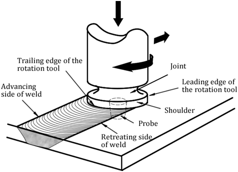
Figure 1 Operating basics of the FSW welding process.7

Figure 2 Different created areas in aluminum FSW bonding.11
The material in the welding zone is exposed to heat and severe deformation. The maximum temperature in the FSW process occurs in this zone. Depending on the welding variables, the maximum temperature about 6061 alloy and 7075 alloy respectively is 400 °C and 480 °C.14,16 Due to the high deformation and relatively high temperature, a dynamic recrystallization is performed in the welding zone, which modifies the microstructure of this region that result in creating a grain size structure between 2 and 10 micrometers.15,17 As a result of the FSW process, the welding zone is seen as a ring structure, such as onion rings (Figure 3).18,19 The cooling rate in the welding zone makes only stable phases grow and prevents making additional phases. Another point is that in this region the crystallization process changes from homogeneous to non‐homogeneous state, which occurs due to accidental crystallization of sediments on dislocations.17,20
The unique feature of the FSW process is creation of an area between the weld region and the base metal called the area affected by mechanical operations. This area experiences the plastic deformation and heat together. Highly deformed structure with more elongated grains of the base metal under upward flow pattern around the weld zone is one of the TMAZ features.13,21–23 This region such as weld zone is not subjected to plastic deformation, so recrystallization, due to lack of plastic strain, does not occur. However, in a few cases have been reported that in this area dynamic recrystallization phenomenon is partially occurs.22,24 Figure 4(a) shows the severe distortion of grains in TMAZ. Feng and his colleagues19 have found that the grains have high density of dislocations that are accompanied by an extensive lattice of fine grains in TMAZ (Figure 4(b)). Based on the results of Feng and his colleagues’ studies, Sedimentary particles of the second phase often grow in the grains or in the grain boundaries of TMAZ due to the heat generated by the FSW process (Figure 4(c)).
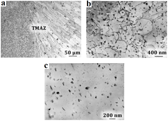
Figure 4 a) Optical microscope image of TMAZ, b) The TEM image of TMAZ shows the high density of dislocations, c) TEM image of the sedimentary particles growth in TMAZ.19
After TMAZ, there is a heat affected zone. This area is only affected by the thermal cycle, but plastic deformation does not occur. Mahoney et al.25 have characterized HAZ in heat treatable aluminum alloys, that materials should experience a temperature of more than 250°C in HAZ. The heat affected zone maintains a grain structure similar to that of base metals. In any case, the application of temperatures above 250 °C will have an important effect on the structure of sediments. The reports of Azimzadegan et al.26 showed that if the input heat to the HAZ is low, or the ratio of the rotational speeds to the progressive speed is low, the boundary between the sediments and the matrix in this zone becomes almost rough. Figure 5 shows the effect of high and low ratios of the rotational speeds to the progressive speed on the HAZ microstructure.
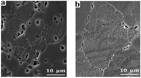
Figure 5 SEM image of HAZ with two different ratio of the rotational speed to the progressive speed: a) Rotational speed: 1300 rpm and progressive speed: 40 mm/min, b) Rotational speed: 1000 rpm and progressive speed: 80 mm/min.26
Effective variables in FSW process
The FSW process is a solid state welding method that is accompanied by complicated material movement and severe plastic deformation. The welding variables, tool geometry, and joint design have a great influence on the heat distribution, materials flow pattern, formed structure, and quality of the materials connection.27 FSW welding variables are as follows: Tool’s rotation speed ( ), traverse speed (v), Applied pressure (P), thickness of work piece (t), pin profile, angle of deviation, pin height, pin direction, blockage and inhibitor forces.28,29
Rotational speed is a very important parameter, which plays a crucial character on the material flow and heat generation, thereby manipulating the microstructures and mechanical properties of joint.30–31 Thus, control of rotational speed during welding has become a critical matter for sound weld. As the tool rotation speed increases, the possibility of mixing the deformed materials in the weld zone will increase, which is considered a positive variable. However, with increasing pin rotation speed the speed of the shoulder increases too, which will cause more heat in the jointing area, because about 95% of the total heat generated by the shoulder. Also, with increasing rotation speed, the amount of generated heat is increased and the size of the pieces taken from the material entering the matrix is increased. This reduces the strength of weld metal. On the other hand, increasing the rotation speed causes porosity at the welding surface, which leads to an imperfection in the weld metal. At low rotation speeds, the thickness of the intermetallic structure will be reduced. However, due to the decrease in the rotation and its passing through a minimum state speed, due to a decrease in friction energy, a proper connection will not be made.32 The results of Kundu et al.,33 showed that high tool rotational speed produce smooth welding as compared to low tool rotational speed. Schneider et al.,34 showed that the rotational speed has a noteworthy effect on the shape of weld zone and joint strength. Moshwan et al.,35 showed the if the rotational speed be 3000 rpm, then all welds between AA 5052–O plates will be sound welded joints with smooth surface appearances. Also, Thangarasu et al.,36 showed that higher rotational speed provided homogenous distribution of TiC particles in the AA6082 matrix while lower rotational speed caused poor distribution of TiC particles in the surface composite.
As the traverse speed progresses, the heat transfer rate decreases between the weld zone and the work piece. Therefore, the effect of the welding process will be observed in the smaller region of the welding edges. On the other hand, by increasing traverse speed, the process speed will increase and distortion will reduce. Also, with increasing traverse speed, the temperature gradient generated in different weld zones will decrease. When the traverse speed is changed, it should be noted that the traverse speed changes must be accompanied by changes in the rotation speed. Otherwise defects, such as cavity and porosity, are formed in the weld zone. For each traverse speed, there is a particular rotation speed that generates flawless welding. This is the basis of the formation of high‐speed FSW welding.32,37 Nansaarng & Chaivanich38 examined the effects of various welding variables on the mechanical and microstructural properties of the Al1100 and Al6063 alloys connection. Their results show that different rotation speeds result in leading to achieve different hardness, while the traverse speed does not effect on the stiffness and hardness of the connection. The results of Hema et al.,39 Showed that the effects of traverse speed on the mechanical properties of the joint, such as hardness and tensile strength, is greater than the rotational speed. Giraud et al.40 showed that when the traverse speed increases, the interface between both base metals (AA7020‐T651 and AA6060‐T6) becomes disrupted on the cross weld direction but it becomes cyclical on the welding direction.
Tool design is the most effective variable in the FSW welding.41 Friction variables, plastic flow of materials, welding ductility pattern, welding zone size, welding speed, tool strength, and heat transfer rate and working temperature are control by tool geometry.42–43 Figure 6(a) shows a schematic of FSW welding tool. As can be seen, welding tool consists of two parts shoulder and pins. Shoulder and pin, depending on the application, have different shapes. In general, the shoulder is used in a flat shape and the pin is used in the form of a truncated cone with thread (Figure 6 (b)). But for special occasions, by creating threads on the surface of the shoulder and making the surface concave, it prevents the plastic materials being pulled out of the shoulder to around of the weld area and creating a flash.43 The contact and friction between the shoulder and the work piece create the greatest heat. The proportion of pin to shoulder size is very important in generating heat and the design of bulges and symptoms does not have a significant effect on them.42 Investigations by Perk et al.,44 showed that, with increasing shoulder diameter (SD) and welding pitch (WP) the heat input to the binding zone is increased, and in this case, cooling rate decreases, which results in increased grain size in the TMAZ region.
In the design of the shoulders, by creating a groove on the surface of shoulder or changing its cross‐section, it may reduce the heat loss from the work piece surface. This work makes it possible to create a better welding by applying a higher vertical force on the tool. Reduction in the diameter of the pin, the amount of tool’s wear will increase and the connection will be inappropriate. On the other hand, the increase in pin diameter has no effect. The approximate diameter of the pin is about the thickness of the sheet. The type of tool used in this welding method should be such that it can withstand high temperatures.45 In the FSW method, W, Mo, tungsten carbide and PBCN alloy tools are used.19 The type of the using tool will be selected based on the type of material to be connected. The tools used for aluminum alloys are more likely to be selected from the H13 tool steel.19,46
Microstructural studies
Researchers have concluded that the FSW welding variables, the tool design, and the alloy have a direct effect on the morphology and structure of grains and sediments.47 The distribution of intense plastic deformation and creating high temperature in the stir zone during the FSW process leads to recrystallization, expansion of the weld structure in the stir zone and the dissolution and expansion of sediments inside and around the stir zone. The microstructure generated by the FSW process is affected by various variables. The change in the welding variables creates a different microstructure in comparison with the previous one. By changing joint microstructure, mechanical properties evolve too. Many researchers have investigated microstructures of FSW.48,49 Somasekharan & Murr50 showed that after the friction welding of the Al6061 alloy to the magnesium alloys by moving from the Al6061 alloy metal base to the joint zone, the size of the alloy grains significantly is decreased. Moreira and his colleagues by investigating the microstructural behavior of the Al6061 and Al6082 alloys’ joint concluded that due to the high strain after plastic deformation, resulting from the friction welding of these alloys, the joint zone was more susceptible for recrystallization than other areas.51 Ahmed et al.,52 showed that the difference between the structure of grains and the sediment in the matrix of two dissimilar alloys has a major impact on the crystallization behavior and, therefore, the final structure of the weld region. Mahoney25 and his colleagues have shown that the difference between different weld zones is in experiencing a certain temperature and plastic deformation, which has a different microstructure and properties. HAZ is a region where is only under the influence of temperature due to friction and, unlike TMAZ, there is no plastic deformation there. These results indicate the importance of the effect of the speed ratio on the microstructure and the final properties of the aluminum alloys FSW joint. It is well accepted that the dynamic recrystallization during the FSW process produces fine grains in the weld zone. The welding parameters, tool design, chemical composition of work piece, work piece temperature, vertical pressure and cooling rate have a great influence on the size of the recrystallized grains.2 Benavides and colleagues53 have done a great deal of research on the effect of the work piece temperature on the grain size in the 2024 alloy welding. They reported that if the initial temperature of the work piece is reduced by using liquid nitrogen from 30 to ‐30 °C, the grain size in the weld zone increases in the upper regions and decreases with the distance from the weld center in each side, which is completely due to temperature changes in the connection area.14,53 Another study showed that in the Al2024‐T6, Al5083‐O, and Al7075‐T6 alloys the maximum temperature in the weld zone will increase by increasing in the rotation speed to the traverse speed ratio.54 The investigation of aluminum alloys microstructure has shown that in connection of these alloys, according to selected parameters for welding, structural strengthening sediments may be dissolved, grown and re‐deposited in the weld zone and a combination of these mechanisms have been confirmed in previous studies.15,27–28 The results of Bayazid et al.,55 showed that by increasing rotation speed, when the other variables are constant, the average size of the grain, in the weld zone, becomes smaller. It should be noted that the grain size in the weld zone affects the joint tensile strength.27 But it has been pointed out that the rotation speed increasing causes the heat to rise in the weld zone, which, due to the low dissolution temperature of aluminum, causes the secondary phase particles to dissolve.46 They55 concluded that increasing the rotation speed to an optimal value, due to grain size reduction in the weld zone, is useful. However, its excessive increase, due to the increase in the input heat, cause dissolution of secondary precipitation particles and has devastating effects. In general, the separation of traverse speed and rotation speed in the FSW welding process is not correct. Somewhat with constant consideration of other variables, the metallurgical and mechanical behavior of the connection can be predicted with traverse speed variations. Also, Bayazid56 showed that with changes in traverse speed, the slope of the weld zone boundary and TMAZ also be changed. They found that the boundary between the weld zone and the TMAZ region tends to get more slope when traverse speed is reduced. However, the results of Gemme et al.,47 showed that the traverse speed does not have much effect on the geometry of the weld zone. Although their research results on the alloy 7075 at various traverse speeds showed that the boundary between the weld zone and the TMAZ zone was changed. In another study, Kumar57 examined the behavior of the FSW joint of some of the 7000 alloys. Their results showed that the microstructure pattern in the bonding region for non‐homogeneous 7000 group is very similar to onion layers. Kumar's results showed that the onion model of the weld zone varies in different traverse speeds. Therefore, the mixing of matter in the joining area depends on the traverse speed. Cavaliere et al.,58 have investigated the behavior of the nonhomogeneous Al2024‐Al7075 connection by FSW. Figure 7 shows the image of the microstructure of the weld zone, HAZ and TMAZ. According to the Figure 7 it is obvious that in the weld zone the structure is shaped like ellipsoidal onion layers. They have reported that type of the structure is the result of the seeds crystallization in the weld zone.
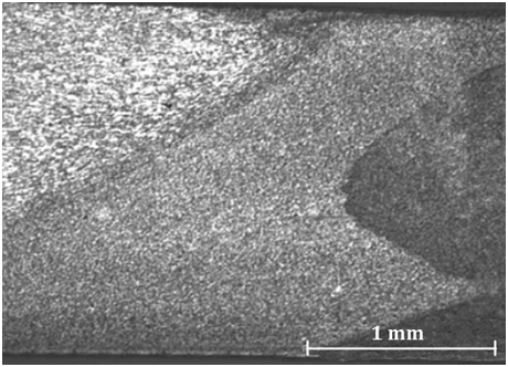
Figure 7 The image of the microstructure of the weld zone, HAZ and TMAZ.58
Also, Azimzadegan et al.,26 investigated the effect of frictional welding variables on the microstructure and mechanical properties of Al7075‐T6 connection. They have examined the effect of the tool rotation speed on the weld pool dimensions which is shown in Figure 8 Their results indicated that the weld zone is considerably becomes widespread due to the acceleration of the rotation speed. Yutaka and colleagues59 also have similar reports about increasing rotation speed at 6063 alloy joints. Increase in the rotation speed, increases the input heat to the joint surface, thereby makes the weld zone wider.
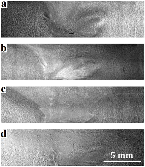
Figure 8 Effect of rotation speed on the weld pool dimensions in 40 mm/min traverse speed, a) 1000, b) 1200, c) 1300, d) 1400 rpm.26
Singh et al.,60 investigated the effect of tool rotation and traverse speed on the mechanical and metallurgical joint properties of FSW AA6082‐T651 alloy. Their results showed that up to 35 mm/min traverse speed and 700 rpm rotation speed, no defect will be observed at the junction, but as soon as the values exceeded from the specified values, the defect will be observed at the junction. At 800 rpm rotation speed and 35 mm/min traverse speed, the Pin Hole defect occurs due to generation of heat or transmission of insufficient material in a progressive side. Similarly, at a 40 mm/min traverse speed and a rotation speed of 800 rpm, the crack and tunnel imperfections are visible in the middle of the coupling cross‐section and on the progressive side, which may be due to the massive movement of the material from the lower surfaces to the upper one.
Mechanical studies
A great deal of research has shown that mechanical properties, including the hardness of the HAZ, and sometimes rarely the hardness of the weld zone of FSW, are greatly reduced.61 For example, Cavaliere's and his colleague’s by study the area of the two FSW cross‐section micro hardness of Al2024 and Al7075 alloys showed that the hardness of the weld center is 150Hv and the hardness of both sides of the joint after reaching the peak, distance 2mm from the weld center, is decreased.58 The results of Al‐Badrawy and his colleagues6 on the weld cross‐sectional area of Al7075 alloy FSW showed that the bond strength is reduced compared with the base metal. They attribute this to refine the grain size62 of the alloy in junction zone. Khan et al.,63 showed that lowest strength for dissimilar joint is primarily due to non‐homogeneous movement of base materials consequent to differences in mechanical and physical properties. Chao and colleagues64 by studying the profile hardness, along the location of the Al2024 and Al7075 alloys joint by the FSW, came to similar results as Al‐Badrawy and his colleagues.6 They observed that the hardness variation in the Al7075 alloy is higher in comparison with the Al2024 alloy.64 Bayazid56 showed that with increasing the rotation speed from 800 to 1000 rpm, the hardness of the weld zone is increased. In their explanation, they pointed out that, with increasing rotation speed, the materials flow in the weld zone increases,59,65 it can be expected that the amount of intense plastic deformation, in the weld zone, as the rotation speed increases, cause decrease in grain size and the hardness of this area increases. In this research, they have pointed out that the reduction in hardness in HAZ is greater at rotation speed of 1,000 rpm. They reported that the cause of this phenomenon is excessive produced heat due to the high rotation speed around the joint area, and thus the increase in grain size and sediment particles in HAZ. Ren et al.,22 also reported that increase in rotation speed, increases the grain size and sediment particles in the HAZ. Meanwhile, Bayazid et al.,55 reported that reduction in the hardness of the weld zone because of an increase in rotation speed from 1600 to 2000 rpm is due to dissolution of secondary sediments in the weld zone. Gaafer et al.,65 reported that in this case, the hardening phenomenon through secondary particles, overcomes grain size reduction. In fact, the dissolution of the sediment has a greater effect on the hardening of the weld zone, rather than the reduction in the grain size due to the increase in the rotation speed, which increases the hardness. Research55 shows that the rotation speed and tensile strength of the heterogeneous connection of 6063‐7075 initially have a direct relation, but after a certain value, this relation becomes an inverse one.
They have mentioned that excessive heat increase due to the high friction, resulting from the increase in rotation speed after a certain amount (1600 rpm), results in the dissolution of sediments66 and even local melting in the weld zone29 and reduces the tensile properties of the connection. Reports indicate that, with increasing rotation speed to an optimum level, at a constant traverse speed, the tensile strength of the joint increases (Figure 9).66 However, it should be noted that as the rotation speed of the pin increases, the rotation speed of the shoulder increases too; this will cause more heat in the joint area, because about 95% of the total heat, generated by the shoulder. Also, by increasing rotation speed, the amount of generated heat increases and the size of the cut pieces of the material entering the matrix, increases. This reduces the strength of the weld metal. On the other hand, increase in the rotation speed causes porosity at the welding surface, which leads to the formation of imperfections inside the weld metal.56
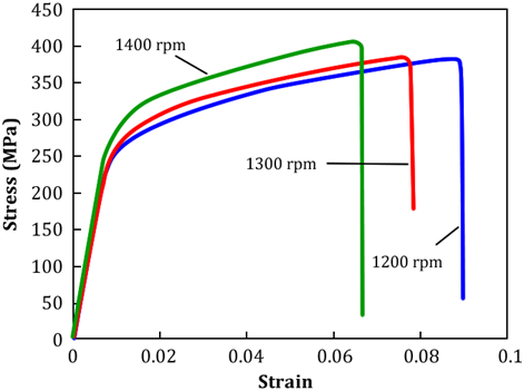
Figure 9 The effect of increasing the rotation speed on the tensile strength of the 7075 alloy.66
The report by El‐Danaf et al.,67 shows that as the traverse speed increase, elongation percentage of 7075‐6063 joint decreases. Also, the results of Palanivel et al.,68 show that with increasing traverse speed in range of 50 to 75 mm/min, the similar joint tensile strength of the 6351 and 5083 alloy, after reaching a maximum value, is reduced. They found insufficient heating the reason of the reduction in the joint tensile strength, after reaching the maximum value. It should be noted that the position of similar sheets, in terms of traverse and non‐traverse, is not important, but if sheets are dissimilar, this variable is important.
Investigations of Cavaliere et al.,69 on connection of dissimilar 2024 and 6082 alloys showed that the bonding strength is higher when the 2024 alloy (with higher strength) is on the traverse side. However, the fatigue and tensile strength properties of the dissimilar joint of 6082‐ 2024 are the highest when the 6082 alloy is in traverse side. Based on cross‐sectional images of a number of dissimilar joints of 6063‐7075, provided by Bayazid et al.,55 it can be concluded that when the softer metal (6063) is placed on the non‐traverse side, the weld zone achieves a screw structure (Whirlpool) that containing layers of two 6063 and 7075 alloys. This type of screw structure is affected by welding variables and threads on the surface of the pin.70 But when the 6063 alloy is on the traverse side (AS), there is no mixing between the two alloys in the weld zone, and the boundary between the two alloys is completely separable. They55 have reported that no fracturing of the alloys surface oxides, at the interface boundary, by the tool, cause to create such a connection. Surface oxides prevent the mixing of two alloys due to high melting temperatures, such as an impenetrable layer. It has been reported that in order to solve this problem, the tool should be diverted to a very small amount (less than 1 to 2 mm) from the joint line to the metal with greater strength.70‐73 Another studies74–75 also show that, for dissimilar connections, when the alloy with high strength and hardness is on the traverse side, the tensile strength of the joint is greater. Researchers70‐73 have pointed out that due to surface oxides and strain problems that make material to have easier plastic deformation, it is better that the material with higher strength and hardness be placed on the traverse side.
Post weld heat treatment (PWHT)
The heat treatment after welding is one of the tasks that improve the mechanical and microstructural properties of the joint. Cerri et al.,76–77 examined the effect of heat treatment after welding on dissimilar bonding of 2024 and 7075 alloys. Barcelona and colleagues78 by studying the effect of heat treatment after welding on the 2024 and 7075 alloys’ bonding concluded that this operation can improve the general properties of the FSW bonding. Their results showed that the heat treatment after PWHT welding on the 7075 alloy joint causes a more uniform distribution of sediment particles in different regions (As shown in Figure 10). As shown in Figure 10, it is observed that by performing heat treatment after welding, the distribution of particles near the weld zone changes from curve state to a uniform state. Mahoney et al.,79 showed that if the aging process is carried out at a lower temperature, the tensile properties of joint in the 7075 alloy FSW change. Figure 11 shows the TEM image of the failure zone of the joints with both the heat treatment and without the heat treatment. Mahoney et al., have reported that sedimentary particles of MgZn2 in two different sizes (15 to 40 nm and 30 to 40 nm) have been seen in the TEM image of the failure zone of the joint that has not been heat treated, (Figure 11(a)). All of the sediment particles they have reported were of disc type with thickness of 10 nm. While the aging heat treatment after welding for 24 hours at 121°C, increases the particle size to a range of 50 to 75 nm.
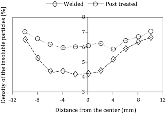
Figure 10 Distribution of sedimentary particles in different joint zones, before and after heat treatment (PWHT).78
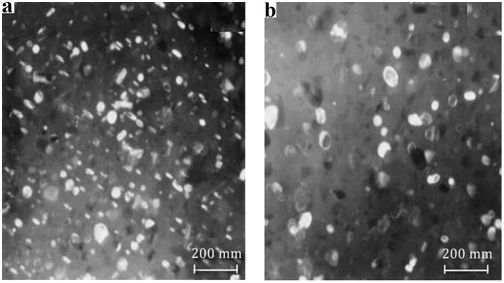
Figure 11 TEM dark field image of sedimentary particles (MgZn2) fracture area; a) without heat treatment; b) with aging heat treatment.79
Grain growth in the weld zone, which is highly vulnerable, is one of the things that occur after the heat treatment. Krishnan80 showed that the heat treatment after welding (dissolving for 1 hour at 540 °C and aging at 175 °C for 8 hours), as shown in Figure 12 & Figure 13, not only caused abnormal grain growth in the weld zone, also cause increase in the grain boundary thickness.
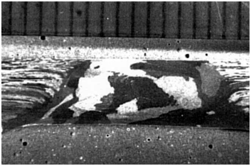
Figure 12 Grain growth in 6061 alloy after heat treatment (dissolution for 1 hour at 540 °C and aging at 175 °C for 8 hours).80
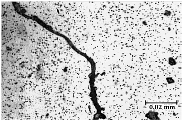
Figure 13 Thickening of grain boundaries in 6061 alloy FSW after the heat treatment (dissolution for 1 hours at 540 °C and aging at 175 °C for 8 hours).80
Oertelt et al.81 showed that the post weld heat treatment on the 2195 alloy reduce the dislocation and the sediment particles of the second phase at the grain boundaries. Also, Singh et al.,82 by doing heat treatment after the welding on the 7039 alloy’s FSW joint showed that the grain size in the TMAZ was greater than the weld zone but smaller than the grain size in HAZ after carrying out the heat treatment. Researches have shown that the heat treatment on the 7039 alloy’s FSW joint causes a change in location and failure mechanism of the samples in the tensile test.83 Krishna et al.,84 showed that the heat treatment after welding on the FSW joint of dissimilar 2024 and 6351 alloys increases the hardness and tensile strength of the joint. In the studies of Goloborodko85, Lim86 & Yeni87 it is mentioned that a dynamic recrystallization phenomenon occurs in this area due to the severe plastic deformation induced by the FSW process in the weld zone. This issue creates a region with very tiny and coaxial particles. Cerri77 by performing solution treatment for 1 hour at 400 °C on overlap joint of 2024 and 7075 alloys while increase the hardness of the weld zone by 10%, almost reached to a completely uniform hardness throughout the joint profile. Attallaha et al.,88 also by performing solution treatment on 2029 alloy, faced to an abnormal grain growth (AGG) in the weld zone. Their solution was carried out at 540 °C for 70 minutes. It should be noted that the grain growth reduces the joint toughness. The results of Fuller et al.,89 showed that the natural aging of the 7075 alloy after the FSW produced a weld area with high‐density of sediment particles of less than 5 nm and including a low density of sediment particles of 50 nm. Sato90 reported that the hardness of the weld zone is strongly affected by sediment and the effect of the grain size is not as much as the size of the sediments. Bayazid and colleagues researches91 on the grain size and the weld zone of the similar joint deposits of the 7075 alloy, after cyclic dissolution treatment without aging treatment, showed that the grain size in the weld zone becomes much larger. However, joint strength increases after cyclic solving treatment. It is expected that in spite of the grain growth in the heat treatment cycle, the strength of the sample is decreased. But they have pointed out that the reinforcement mechanism through the sediment particles in the weld zone greatly neutralizes the effect of grain growth. They91 also reported that the rapid cooling of the weld sample after the solution treatment causes a super saturation state84 along with a large number of vacancies. Subsequently, aging operations create a large number of homogeneous sediments with triangular geometry in the matrix, which the sediments are cause of strength and toughness. The uniformity of hardness in the jointed samples is one of the other advantages of doing heat treatment after welding.80,92–93
Defects created in the FSW process
Many factors cause defects in the FSW. One of these important factors is insufficient heat in the joint zone. In some cases, due to low rotation speed or high traverse speed, there is not enough heat in the joint zone, which causes the lack of successful connection and, in most cases, creates defects, including a tunnel cavity. Many researchers94–95 have linked the presence of a tunnel cavity in the connection to the low temperature created in the joint zone, which the presence of this defect causes the connection to fail. It has been reported that improper fixture is also the cause of this defect.95 Of course, the lack of proper pin contact with sheet surfaces is also a factor that reduces heat and thus creates a tunnel cavity defect. Figure 14 shows the SEM image of a created tunnel defect in a non‐homogeneous connection of 7075‐6063 with a rotation speed of 800 rpm and a traverse speed of 120 mm/min.56
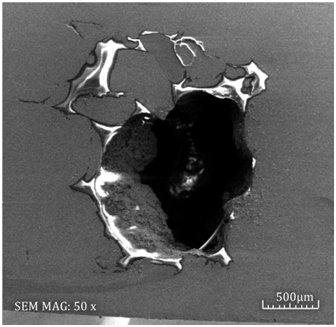
Figure 14 The SEM image of the 7075‐6063 joint with a rotation speed of 800 rpm and a traverse speed of 120 mm/min.56
Surface cracks and cavities caused by high input heat in this process are also common defects. The opposite of the situation when the tunnel cavity is created, when the produced heat is too high, surface cavities are observed at the upper surface of the joint (Figure 15).56 Previous reports indicate that if all the main factors involved in the FSW welding are met, there is a suitable range for the rotation speed and traverse (weld window), as shown in Figure 16, it is only in this range that a good connection, due to thermal problems, is made.96 Thus, one of the most important issues in the FSW is to identify this range.
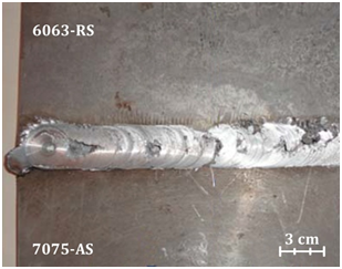
Figure 15 Image of cavities present at the FSW joint surface of 6063 and 7075 alloys at 2000 rpm rotation speed and 95 mm/min traverse speed.56
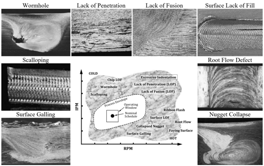
Figure 16 The FSW welding window, along with various defects created in inappropriate conditions.96
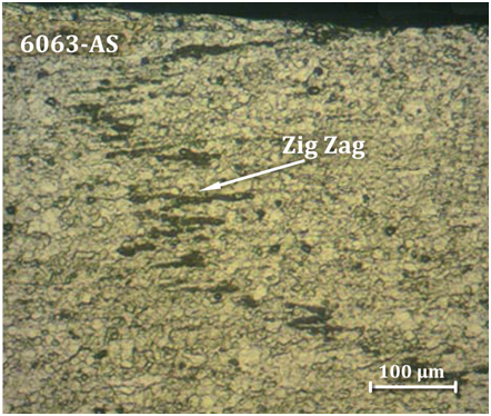
Figure 17 Zig zag defect in non‐homogeneous connection of 7075 RS‐6063 AS; Rotation speed of 1600 rpm and traverse speed of 80 mm/min.56
Another reason for a microscopic defect is the presence of aluminum oxide at the contact surface of the sheets. Due to the high melting point, aluminum oxide does not dissolve in the welding process and remains in junction place as a pore. The existence of these pores creates defects that are called zig‐zag defect.23,97 In Figure 16, an example of this type of defect is found in dissimilar welding of 7063‐7075, which has been reported as the reason for the formation of a softer material in the traversal part.56 According to previous reports,23 the main cause of fatigue failure in samples that are welded by the FSW method is zig‐zag defect. On the other hand, Song et al. reported that when the 5032 alloy is in traversal side, the zig zag defect appears in the weld zone. They reported that the lack of mixing and flow of materials when the 5032 alloy is in re‐traverse side is more difficult than that of the 5032 alloy on the traversal side.48
The present review has confirmed that FSW process which is a solid state welding method is the best process to welding of different alloys of aluminum with an outstanding quality. In the FSW process three different areas including stir zone (SZ), Thermo–mechanically affected zone (TMAZ) and heat affected zone (HAZ) are created. The main factors of this process are tool geometry, rotational speed, traverse speed, tilt angle and target depth which affect the microstructure and mechanical properties. It is clear that, the departure of traverse speed and rotation speed in the FSW welding process is not accurate. Thus, for each metal, there is a window about traverse speed and rotational speed so as to creating sound weld. Also, mechanical properties of the weld is mostly related to the rotational speed, because the rotational speed plays a critical role on the material flow and heat generation. Although, tool design and the type of alloy have direct effect on the morphology and structure of grains and sediments. It should be mentioned that the position of dissimilar sheets have effect on the mechanical properties of the final weld. For the best results, softer metal must be on the non‐traverse side. PWHT can improve the weld’s properties such as hardness in HAZ, if it does not lead to grain growth.
Author declares there is no conflict of interest.

©2018 Bayazid, et al. This is an open access article distributed under the terms of the, which permits unrestricted use, distribution, and build upon your work non-commercially.