eISSN: 2574-9927


Research Article Volume 3 Issue 1
1Universidade Federal de Uberlandia, Brazil
2Departamento de Engenharia de Estruturas, Universidade de Sao Paulo, Brazil
Correspondence: Rodrigo Gustavo Delalibera, Faculdade de Engenharia Civil, Universidade Federal de Uberlandia, Brazi
Received: December 18, 2018 | Published: February 6, 2019
Citation: Sivelli MG, Delalibera RG, Giongo JS, et al. Behavior of pile caps on one steel pile. Material Sci & Eng. 2019;3(1):24-31. DOI: 10.15406/mseij.2019.03.00084
This paper reports the numerical analysis of several pile caps, supported on one steel pile. The variables studied were the column contact area, the pile embedment into the cap and the presence of a bearing steel plate, welded at the pile head. The numerical analysis was based out from a three-dimensional model, set by the finite element method analysis. The results showed that the pile embedment length has a great influence on the mechanical behavior of the reinforced concrete caps, although this aspect has not been well explored analytically or experimentally yet. In addition, it was verified that the pile embedment length has influence over the stress flow and the ultimate strength of the cap. The results also pointed out that a steel plate at the top of the steel pile may lead to a positive effect by improving the load distribution inside the pile cap.
Keywords: pile cap, steel pile, numerical analysis, pile embedment, steel pile connection
Piles are slender linear structural elements, whose purpose is to transfer the load from the superstructure to the soil. The connection between the piles and the superstructure is commonly done by pile caps that, according to the NBR 6118, are volumetric structures used to transfer the load coming from the superstructure to the piles. The first studies of great relevance, regarding the design of pile caps, are from Blévot & Frémy1 however, most of the researches on this area studied pile caps on reinforced concrete piles, leaving a vast field to be explored about pile caps on steel piles. According to Velloso & Lopes,2 the main disadvantage of using steel piles, in relation to other types of piles, is its high cost. Still, in some situations the use of steel piles is economically viable as they can be driven in almost any kind of soil and are highly effective against the vibration on the driving process. In agreement with NBR 6122,3 connection between the pile and the cap can be made with an embedment length of the pile in the cap of 20 centimeters and, in addition, a helical reinforcement may be used. After its review, the NBR 61224 suggests only that the connection must be made by using either steel plates on top of the piles, stirrups or steel rebar welded to the pile. Fundações Teoria e Prática5 recommends that a helical reinforcement is placed over the embedment length of the steel pile in the cap. Pfeil6 suggests that straight rebar must be welded over the embedment length of the steel pile, with the addition of helical reinforcement, and that the embedment length of the steel pile must be at least 30 centimeters.
The Manual de Especificações de Produtos e Procedimentos da ABEF7 recommends that either an embedment length of 20 centimeters with helical reinforcement or an embedment length of 5 centimeters with straight rebar welded on the pile. Currently one of the most used constructive methods consists on welding a steel plate on top of the steel pile with the addition of welded rebar, as recommended by Pfeil.6 the manual from Gerdau,8 however, does not recommends this kind of connection due to its technical difficulty of execution. The same manual suggests the usage of helical rebar around the embedment length of the steel pile and rebar welded on the pile, to improve its anchorage. The SODH9 (State of Ohio Department of Highways) conducted tests on 47 real scale pile caps on one steel pile, concluding that the usage of a steel plate on top of the pile doesn’t improve the strength of the connection and that the failure of the cap by tensile stresses transverse to the principal compressive stresses, that arise due to the effect of partially loaded block, is the main reason of failure of the caps. However, the bearing system used by the authors, on which an entire face of the cap is in contact with the ground, doesn’t represent well the actual behavior of one pile caps, since they usually have the load applied on its upper surface by a column of much smaller transverse area. Slutter10 tested 2 real scale pile caps on six steel piles each. The author concluded that the usage of plates on top of the steel piles doesn’t affect the bearing capacity of the pile cap. The author further notes that the distance between the axis of the steel piles and the edge of the pile cap must be adequate to allow proper anchorage of the reinforcement. It is observed, therefore, divergences between the experimental results from SODH9 & Slutter10 some recommendations from the technical literature, mainly about the embedment length of the steel pile. This shows that there are still many doubts about the behavior of pile caps on one steel pile, and so this paper is justified by the scarce studies and standards about pile caps on one steel pile.
Objective
This paper had the objective on studying, trough numerical analysis, the influence of different variables over the structural behavior of pile caps on one steel pile subjected to centered load. The variables studied were: the embedment length of the pile in the cap; the type of connection between the pile and the cap; the dimensions of the column transverse section which, in order to simplify further experimental tests, was considered as being a steel plate of equal transverse section whose only function was to load the pile cap. It was adopted embedment lengths of 5cm, 15cm and 25cm, while the dimensions of the column cross section were adopted as 100cm² (10cm x 10cm), 200cm² (10cm x 20cm) and 300 cm² (10cm x 30cm). The types of connection studied were: connection between the pile and the cap by a steel plate welded on top of the pile and by direct contact between the steel pile and the concrete. The type of connection only varied on the models with the embedment length of 5 cm. Figure 1 shows the three-dimensional model and the variables studied.
The behavior of pile caps on one steel pile was studied by non-linear numerical analysis utilizing the software ANSYS®, which uses the finite element method on its solutions. The geometrical properties of the numerical models were defined by analytical criterion, considering that the behavior of the pile cap on one steel pile is similar to that of a partially loaded block. The partially loaded block model used was the one suggested by Langendonck11 at last, an analysis of variance was made in order to verify the variables that have the most influence over the bearing capacity of the pile caps.
The dimensions of the pile caps and the columns were defined as shown on Figure 2. The width ap was kept constant and equal to 10cm, while the length bp was taken as 10cm, 20cm and 30cm, as mentioned before. The dimensions of the steel piles were considered as being the same dimensions of the steel profile W 150 x 18, which was chosen to be used in a future experimental study. Since the main objective of this paper is to understand the structural behavior of pile caps on one steel pile, it was also considered that the load applied to the cap is centered and there are no beams holding the caps horizontally, such beams are important to provide stability to the piles. Table 1 shows the geometrical properties from the models studied. Each model was named according to the variables analyzed, such that means: embedment length of 5cm; – column cross-sectional area equal to 10 x 10cm²; S/P - models with no steel plate on top of the pile; C/P – models with steel plate on top of the pile.
Model |
Embedment length (cm) |
ap (cm) |
bp (cm) |
Plate |
|
5 |
10 |
10 |
No plate |
|
5 |
10 |
20 |
No plate |
|
5 |
10 |
30 |
No plate |
|
15 |
10 |
10 |
No plate |
|
15 |
10 |
20 |
No plate |
|
15 |
10 |
30 |
No plate |
|
25 |
10 |
10 |
No plate |
|
25 |
10 |
20 |
No plate |
|
25 |
10 |
30 |
No plate |
|
5 |
10 |
10 |
With plate |
|
5 |
10 |
20 |
With plate |
|
5 |
10 |
30 |
With plate |
Table 1 Geometrical properties of the models
Design of the reinforcement
According to Langendonck11 the load applied to the cap is transferred to the piles by inclined struts which are balanced by transverse tensile stresses. The tensile stresses have a tendency to produce cracking and, therefore, the analytical design must provide reinforcement for such stresses. To this end, the cap on one pile is considered to have a behavior analogue to the one of a partially loaded block. Partially loaded blocks were studied by Langendonck11 & Leonhardt & Monnig12 & Fusco8 among others. Fusco8 states that, in such cases, the external load propagates non-uniformly over the length lo, as shown on Figure 3. The author assumes that the length lo is subjected to a triaxial state of stress, with compressive stresses (σccz), and transverse tensile stresses (σcty and σctx). According to Langendonck11 the length lo, shown in Figure 3, is equal to the largest dimension of the area on which FC0 is applied (Saint-Venant Principle). Figure 4 illustrates the model suggested by Langendonck11 for the design of the reinforcement needed to resist the transverse tensile stresses. In line with Langendonck11 the tensile resultant (Rtt) may be obtained by Eq. (1), which is found by static equilibrium considering Z as equal to 0,445∙A, where: Rtt is the tensile resultant (kN); FC0 is the load applied to the block (kN); α is the dimension over which the load is applied, in the considered direction (cm); A is the dimension over which the block reacts to force applied, in the considered direction (cm).
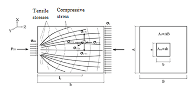
Figure 3 Model recommended by Fusco8 for partially loaded blocks.
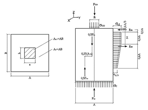
Figure 4 Model recommended by Langendonck11 for partially loaded blocks.
(1)
For the design of the pile caps studied on this paper the partially loaded block model from Fusco8 shown on Figure 3, was readjusted to the one shown on Figure 5. On this model the bottom of the partially loaded block is replaced by the top of the pile. However, the area of the cross-section of the pile on its top was taken as being equal to a rectangle surrounding the steel profile as shown on Figure 5. This simplification is justified by the fact that there are no analytical models corroborated by the technical literature that takes into account the specific geometry of the steel profile used on this study. The model from Figure 5 is then used along with Eq. (1) in order to determine the tensile resultant on both horizontal directions of the models studied. The maximum force applied to the column was verified in line with Eq. (2), recommended by the NBR 611813 where: fcd is the compressive strength of the concrete (MPa); ACO is the column cross-sectional area (m²); AC1 is the pile cross-sectional area (m²).
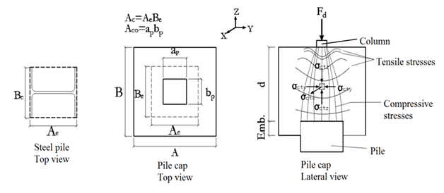
Figure 5 Partially loaded block model adapted from Fusco8 to the case of a pile cap on one steel pile.
(2)
The concrete compressive strength was taken as 25MPa, whereas the reinforcement yield strength was taken as 500MPa. Consequently, FC0 was determined by Eq. (2) and then used on Eq. (1) in order to calculate the tensile resultant on both horizontal directions and the respective reinforcement needed on each direction. For partially loaded blocks, Langendonck11 recommends using five layers of distributed reinforcement of variable spacing. However, this type of reinforcement, as well as the reinforcement in the shape of a cage, which is more common due to being easy to implement, interfere on stress distribution of the pile cap. As the objective of this study is to analyze the influence of the variables aforementioned, the reinforcement used was horizontal stirrups of 5 mm diameter, spaced equally on six layers, with the distance between layers of 4, 4cm. With this arrangement the reinforcement in each direction was substantially higher than the reinforcement calculated by using the analytical model presented. The detailing of the reinforcement is shown on Figure 6.
Numerical analysis
The structural behavior of the pile caps was studied considering the aforementioned variables: embedment length of the pile; presence of a steel plate on top of the pile; cross-sectional area of the column. The pile cap was modeled as a cube of constant volume, with compressive strength of 25MPa. The other mechanical characteristics of the concrete were determined in accordance with the recommendations from the NBR 611813 by considering the aggregates of basaltic origin and the cracking and plastic behaviors of the concrete. For the steel pile, the mechanical properties of the ASTM A52 steel were used, with elastic modulus of 200GPa, Poisson coefficient of 0,3 and yield strength of 345MPa. The steel rebar was modeled considering the mechanical properties from the CA-50 steel, with elastic modulus of 210GPa, Poisson coefficient of 0,3 and yield strength of 500MPa. The numerical analysis was based on the studies of Delalibera & Giongo14 & Delalibera et al.,15 & Delalibera & Giongo16 which defined the parameters used on their numerical analysis for the concrete based on the experimental results from Mautoni17 & Adebar et al.18
Definition of the finite elements
The finite element used for modelling the concrete was the Solid65, which allows for the consideration of non-linearity and has the capacity of simulating cracking, crushing and creep. For the rebar, it was used the finite element Link180, which functions exclusively under tensile or compression. The plastic behavior of the rebar was simulated by a bilinear kinematic hardening model. Perfect bond between the rebar and the concrete was considered. The finite element used for modelling the steel piles and the steel plates was the Solid185. For the plastic behavior of the steel under the Solid185 finite element, a bilinear kinematic hardening model was also implemented.
Definition of the finite element mesh
The finite element mesh implemented was the Hex Mapped Mesh, provided by the software ANSYS®, with maximum dimensions of 2,5cm. In order to model the concrete, the following entry parameters were needed: elastic modulus; Poisson’s coefficient; compressive strength; tensile strength; shear transfer coefficients. The shear transfer coefficients were taken as equal to 0,85 for open cracks and 1 for closed cracks. The failure criteria implemented for the concrete was the Concrete criteria, provided by the software ANSYS®, which is similar to the William-Warnke criteria. The force Fco, previously calculated, was applied on the top surface of the column as a uniformly distributed pressure. The influence of the column’s reinforcement over the stress distribution of the pile cap was not taken into consideration on this paper. Such decision is based on the equation recommended by the NBR 611813 which doesn’t consider the column’s reinforcement for calculating the contact pressure between the column and the pile cap. The boundary conditions applied to the pile were of fixed translation on all the nodes from the bottom surface area of the pile. The finite element mesh, as well as the boundary conditions of the three-dimensional model, are shown on Figure 7. For the solution, the load was applied in 100 sub steps, with a maximum of 200 and a minimum of 50 sub steps. For the solution of the non-linear system of equations the Newton-Raphson modified method was used, with a convergence tolerance of 0,5%, for displacements and forces.
In general, the regions of contact between the column and the pile cap and between the pile cap and the steel pile showed a high concentration of compressive and tensile stresses, as well as concentrated cracking. Therefore, it can be said that all models failed because of such concentration of tensile stresses.
Embedment length
Figure 8 shows the force versus displacement of the models on the vertical direction, on a point between the top of the pile and the bottom of the column. By the initial stages of loading the models already showed significant differences of stiffness. It was observed that the stiffness of the pile caps decreased as the embedment length increased. The limit of proportionality, as well as the bearing capacity, were higher on the models with 15 and 25cm of embedment length. In addition, for the same force, such models showed a higher nodal displacement when compared to the models with an embedment length of 5cm. In addition to the analysis of the Force versus displacement behavior, the distribution of tensile stresses on the horizontal directions of the pile cap was also evaluated. The Figure 9 shows the distribution of tensile stresses at failure on the models with a column cross-sectional area of 10 x 10cm². It was observed that, on the models with embedment length equal to 15 and 25cm, the tensile stresses were of lesser intensity, especially on the models with a column cross-sectional area of 10 x 10cm² and 10 x 15cm². It was observed that, on all the models, a higher column cross-sectional area provided a regularization on the distribution of stresses. Such phenomenon favors the bearing capacity of the pile cap. The Table 2 shows a comparison between the forces determined analytically by using the previously described model (Fco) and the failure forces (Fu) of each model.
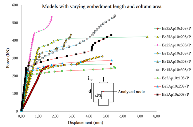
Figure 8 Force versus displacement of the models with variation of the column cross-sectional area as well as the embedment length.
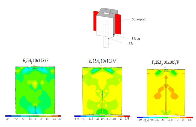
Figure 9 Distribution of tensile stresses at failure, on the models with a column cross-sectional area of 10 x 10 cm².
Model |
|
(kN) |
(%) |
|
312 |
250 |
80,1 |
|
441 |
412 |
93,4 |
|
540 |
430 |
79,6 |
|
312 |
310 |
99,4 |
|
441 |
430 |
97,5 |
|
540 |
541 |
100,2 |
|
312 |
268 |
85,9 |
|
441 |
421 |
95,5 |
|
540 |
534 |
98,9 |
Table 2 Comparison between the calculated forces ( ) and the failure forces ( ) of the models without a plate on top of the pile
Connection by a steel plate
The connection between the pile cap and the steel pile was analyzed with the objective of determining whether a steel plate, welded on top of the pile, has any effect over said connection or not. The Figure 10 shows the force versus displacement on the pile caps with and without a steel plate on top of the pile. As mentioned before, all the models with a variable type of connection had 5cm of embedment length. It was observed that, regardless of the type of connection, the behavior of the pile caps on the initial stages of loading was similar. However, as the load increased, the models with a plate on top of the pile had its bearing capacity and limit of proportionality improved. The Figure 11 shows a comparison between the distribution of tensile stresses on the models with and without a plate on top of the pile (embedment length of 5cm and column of a cross-sectional area equal to 10 x 20 cm²). The Figure 11 shows that, overall, a plate on top of the pile decreased the value of the tensile stresses. In addition, such plate improved the distribution of the tensile stresses on the contact pile-cap, preventing concentration of stresses. The Table 3 shows a comparison between the forces determined analytically by using the previously described model (Fco), adapted from Fusco8 and the failure forces of each model (Fu), found on the numerical analysis.
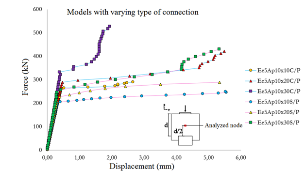
Figure 10 Force versus displacement of the models with and without a steel plate on top of the pile.

Figure 11 Distribution of tensile stresses at failure, on the models with a column cross-sectional area of 10 x 20 cm² and embedment length of 5cm.
Model |
(kN) |
(kN) |
(%) |
|
312 |
250 |
80,1 |
|
441 |
412 |
93,4 |
|
540 |
430 |
79,6 |
|
312 |
289 |
92,6 |
|
441 |
421 |
95,5 |
|
540 |
527 |
97,5 |
Table 3 Comparison between the calculated forces ( ) and the failure forces ( ) of the models with and without a plate on top of the pile
Analysis of variance
An analysis of variance (ANOVA) was used in order to define if the variables studied had a major influence on the structural behavior of pile caps on one steel pile. The variables studied on this analysis were the embedment length of the steel pile in the pile cap (Ee) and column cross-sectional area (Ap), while the response was the bearing capacity of the pile cap (Fu). Only the models without a plate on top of the pile were used on the ANOVA, with an alpha value (α) of 0,05. The F-test, with values given by Montgomery19 was used to determine whether the studied variables were influential or not. The Table 4 shows the results from the ANOVA. It can be observed that the variable embedment length (Ee) doesn’t have substantial influence on the response, while the variable column cross-sectional area (Ap) does have substantial influence on the response. Therefore, it may be said that the column’s geometry is the factor that influences the structural behavior of the analyzed models the most.
Source |
Sum of squares |
Degrees of freedom |
Mean of squares |
|
|
|
78458 |
2 |
39229 |
44,36 |
6,94 |
|
6250 |
2 |
3125 |
3,53 |
6,94 |
Error |
3537 |
4 |
884 |
|
|
Total |
88244 |
8 |
|
Table 4 Analysis of variance
Through the analysis of the results obtained it was shown that the steel plate on the top of the pile improved the caps strength, conflicting with what was encountered by SODH9 & Slutter10 the usage of the steel plate reduced the difference between the force at failure and the force calculated analytically (Fco) for all the models. Therefore, the steel plate made the cap structurally safer, with the contact stresses between the cap and the steel pile more evenly distributed. In accordance with the analysis of variance, the column’s cross-sectional area has more impact on the structural behavior of the caps than the embedment length of the steel pile. Such behavior was expected, as the caps that had larger column’s cross-sectional area had higher bearing forces. However, it is important to note that by maintaining the same column’s cross-sectional area, the caps with a steel plate on top of the pile and smaller embedment length had more bearing capacity. It is concluded, therefore, that the usage of a steel plate on top of the steel pile, as well as the contact area between the cap and the column, are of great importance to the structural efficiency of one steel pile cap. However, further research is still needed for the development of a design model.
Thanks to the Fundação de Amparo à Pesquisa do Estado de Minas Gerais – FAPEMIG, for the financial support given to the development of this and other researches. Thanks to the CNPq – Conselho Nacional de Desenvolvimento Científico e Tecnológico, for the financial support given to the first author for its scientific initiation. Thanks to the company Gerdau for the incentive given for research and for the donation of steel profiles.
Author declares that there is no conflicts of interest.

©2019 Sivelli, et al. This is an open access article distributed under the terms of the, which permits unrestricted use, distribution, and build upon your work non-commercially.